Process for injection molding semi-solid alloys

a technology of semi-solid alloys and injection molding, which is applied in the direction of metal founding, chemical apparatus and processes, etc., can solve the problems of degradation of processing yield, inferior product, and mechanical properties of molded articles, and achieves low porosity, less energy, and high quality articles

Inactive Publication Date: 2003-12-18
HUSKY INJECTION MOLDING SYST LTD
View PDF7 Cites 16 Cited by
  • Summary
  • Abstract
  • Description
  • Claims
  • Application Information

AI Technical Summary

Benefits of technology

[0009] In view of the limitations of conventional SSIM processes discussed above, the present invention provides a process for injection-molding alloys of ultra-high solids contents, in excess of 60%. In particular, the present invention relates to a process for injection-molding magnesium alloys of solids contents ranging from 60-85% to produce high-quality articles of uniform microstructure and low porosity. The ability to injection mold high-quality articles using ultra-high solids contents enables the process to use less energy than conventional SSIM processes, and also to produce articles of near net shape with reduced shrinkage caused by solidification of liquids.
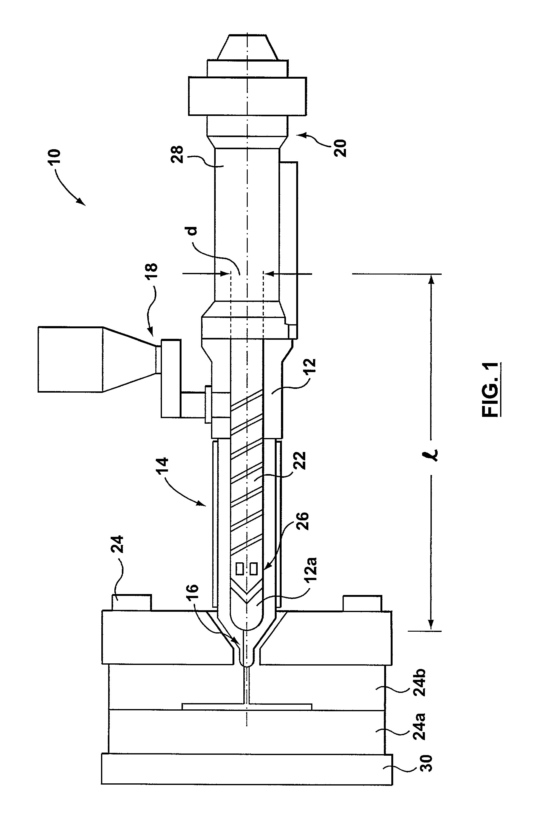
[0033] Motion of the screw portion 22 acts to convey and mix the slurry. A non-return valve 2 prevents the slurry from squeezing backwards into the barrel portion 12 during injection.
[0034] The internal portions of the apparatus 10 are kept in an inert-gas ambient to prevent oxidation of the alloy material. An example of a suitable inert gas is argon. The inert gas is introduced via the feeder 18 into the apparatus 10 and displaces any air inside. This creates a positive pressure of inert gas within the apparatus 10, which prevents the back-flow of air. Additionally, a plug of solid alloy, which is formed in the nozzle portion 16 after each shot of alloy is molded, prevents air from entering the apparatus 10 through the nozzle portion 16 after injection. The plug is expelled when the next shot of alloy is injected and is captured in a sprue post portion of the mold 24, discussed below, and subsequently recycled.
[0044] After the mold 24 is filled with the slurry, the slurry undergoes a final densification, in which pressure is applied to the slurry for a short period of time, typically less than 10 ms, before the molded article is removed from the mold 24. The final densification is believed to reduce the internal porosity of the molded article. A short mold-filling time ensures that the slurry has not solidified, which would prevent a successful final densification.
[0048] It is well established that semi-solid slurries exhibit both solid-like and liquid-like behavior. As a solid-like material, such slurries possess structural integrity; as a liquid-like material, they flow with relative ease. It is generally desirable to have such slurries fill a mold cavity in a laminar-flow manner, thus avoiding porosity caused by gases trapped in the slurry during turbulent flow, which is observed in articles molded from fully liquid material. (Laminar flow is commonly understood to be the streamline flow of a viscous, incompressible fluid, in which fluid particles travel along well-defined separate lines; and turbulent flow is commonly understood to be fluid flow in which fluid particles exhibit random motion.)
[0049] In contrast to conventional wisdom, the examples discussed below indicate that injection under laminar-flow conditions is not critical to achieving high-quality molded articles having a low internal porosity. Instead, a critical factor affecting the success of an ultra-high-solids-content SSIM process is the gate velocity during injection, which affects the mold-filling time. That is, it is important that the mold cavity be filled by the slurry while the slurry is in a semi-solid state, in order to avoid incomplete molding of articles caused by premature solidification. A suitably fast mold-filling time may be obtained by modifying the gate geometry to increase the cross-sectional area of the gate.

Problems solved by technology

SSIM avoids the formation of dendritic features in the microstructure of the molded alloy, which are generally believed to be detrimental to the mechanical properties of the molded article.
The upper limit of 60% was determined based on a belief that any higher solids content would result in a degradation in processing yield and an inferior product.

Method used


Image

  • Process for injection molding semi-solid alloys
  • Process for injection molding semi-solid alloys
  • Process for injection molding semi-solid alloys

Examples


example 2

[0052] EXAMPLE 2 Under the same conditions as Example 1, but with a 50% reduction in the screw velocity (1.4 m / s), corresponding to a gate velocity of 24.32 m / s and a mold-filling time of 50 ms, premature solidification prevented the alloy slurry from completely filling the mold cavity. The weight of the molded article was 90% of that the fully molded article of Example 1. The majority of the unfilled areas was found to be situated at the outer edges of the article. A partial filling of the mold cavity revealed that the flow front improved in comparison with that of Example 1, but still was non-uniform and not completely laminar. This is especially evident in thin-walled regions, where local flow fronts moving from thicker regions solidified instantly after contacting the mold surface. Unexpectedly, despite the reduction in turbulence, the internal porosity of fully molded parts was higher than that measured for Example 1, and had an unacceptably high value of 5.3%. The results of t...


PUM

PropertyMeasurementUnit
velocityaaaaaaaaaa
velocityaaaaaaaaaa
porosityaaaaaaaaaa

Abstract

A injection-molding process injects a semi-solid slurry with a solids content ranging from approximately 60% to 85% into a mold at a velocity sufficient to completely fill the mold. The slurry is injected under laminar or turbulent flow conditions and produces a molded article that has a low internal porosity.

Description

[0001] 1. Field of the Invention[0002] The present invention relates generally to a process for injection molding metallic alloys and, more particularly, to a process for injection molding semi-solid alloys having a high content of solid material.[0003] 2. Related Art[0004] Semi-solid metals processing began as a casting process developed in the early 1970s at the Massachusetts Institute of Technology. Since then, the field of semi-solid processing has expanded to include semi-solid forging and semi-solid molding. Semi-solid processing provides a number of advantages over conventional metals-processing techniques that require the use of molten metals. One advantage is the energy savings of not having to heat metals to their melting points and maintain the metals in their molten state during processing. Another advantage is the reduced amount of liquid-metal corrosion caused by processing fully molten metals.[0005] Semi-solid injection molding (SSIM) is a metals-processing technique ...

Claims


Application Information

Patent Timeline
Patent Type & Authority Applications(United States)
IPC IPC(8): B22D21/04B22D17/00C22C1/00
CPCB22D17/007Y10S164/90C22C1/005B22D17/2281C22C1/12B22D17/00C22C1/00B22D17/10
Inventor CZERWINSKI, FRANKKADAK, DAMIR
Owner HUSKY INJECTION MOLDING SYST LTD
Why Eureka
Try Eureka