
Apparatus and method for thrust vector control

a technology of thrust vector and apparatus, applied in the direction of marine propulsion, servomotors, vessel construction, etc., can solve the problems of increasing cost, reducing reliability and durability, and complex and expensive ducts,

Inactive Publication Date: 2003-04-17
GATEWAY SPACE TRANSPORT
View PDF0 Cites 21 Cited by
  • Summary
  • Abstract
  • Description
  • Claims
  • Application Information

AI Technical Summary

Problems solved by technology

Consequently, complex and expensive ducts, reservoirs, pumps and the like are required.
The complexity of these systems decrease reliability and durability while increasing expense.
Even the coarse control currently available with current thrust vector control systems typically involves overlapping vanes or plates which generate a high amount of friction with one another and / or their housings in operation.
High actuation force again requires a complex and expensive system of hydraulic or mechanical actuators.
Both these systems and auxiliary fine vector thrust control systems present risks of fire, inoperability and engine contamination in case of leaks or other failures.
When high force is required at high thrust levels, present systems are not always capable of providing the required actuation force under all conditions, especially low speed applications such as VTOL.
The expense and complexity of the currently available actuation systems make retrofitting thrust vector control systems onto existing jet engines impractical and expensive.

Method used


Image

  • Apparatus and method for thrust vector control
  • Apparatus and method for thrust vector control
  • Apparatus and method for thrust vector control

Examples


Embodiment Construction

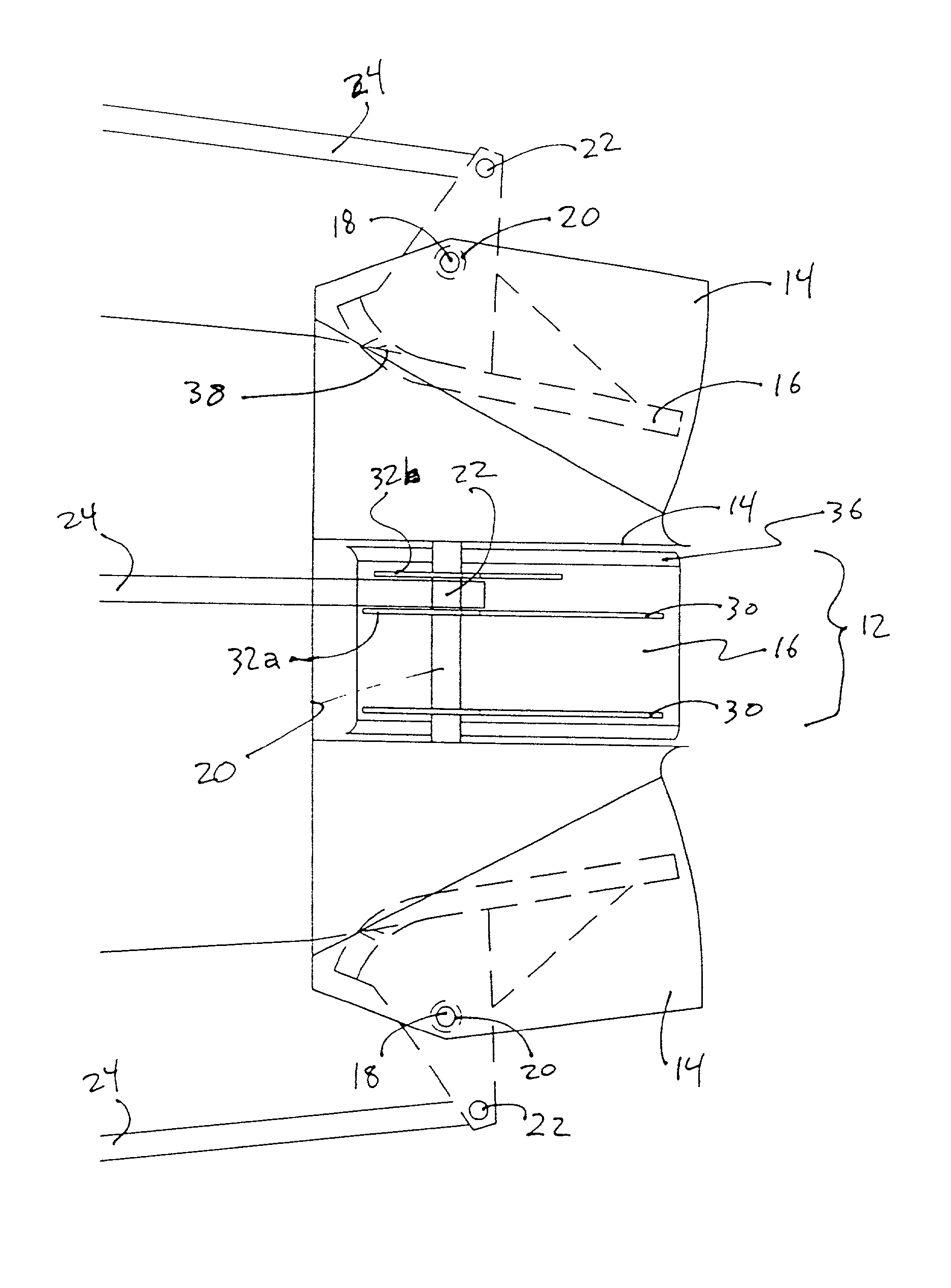
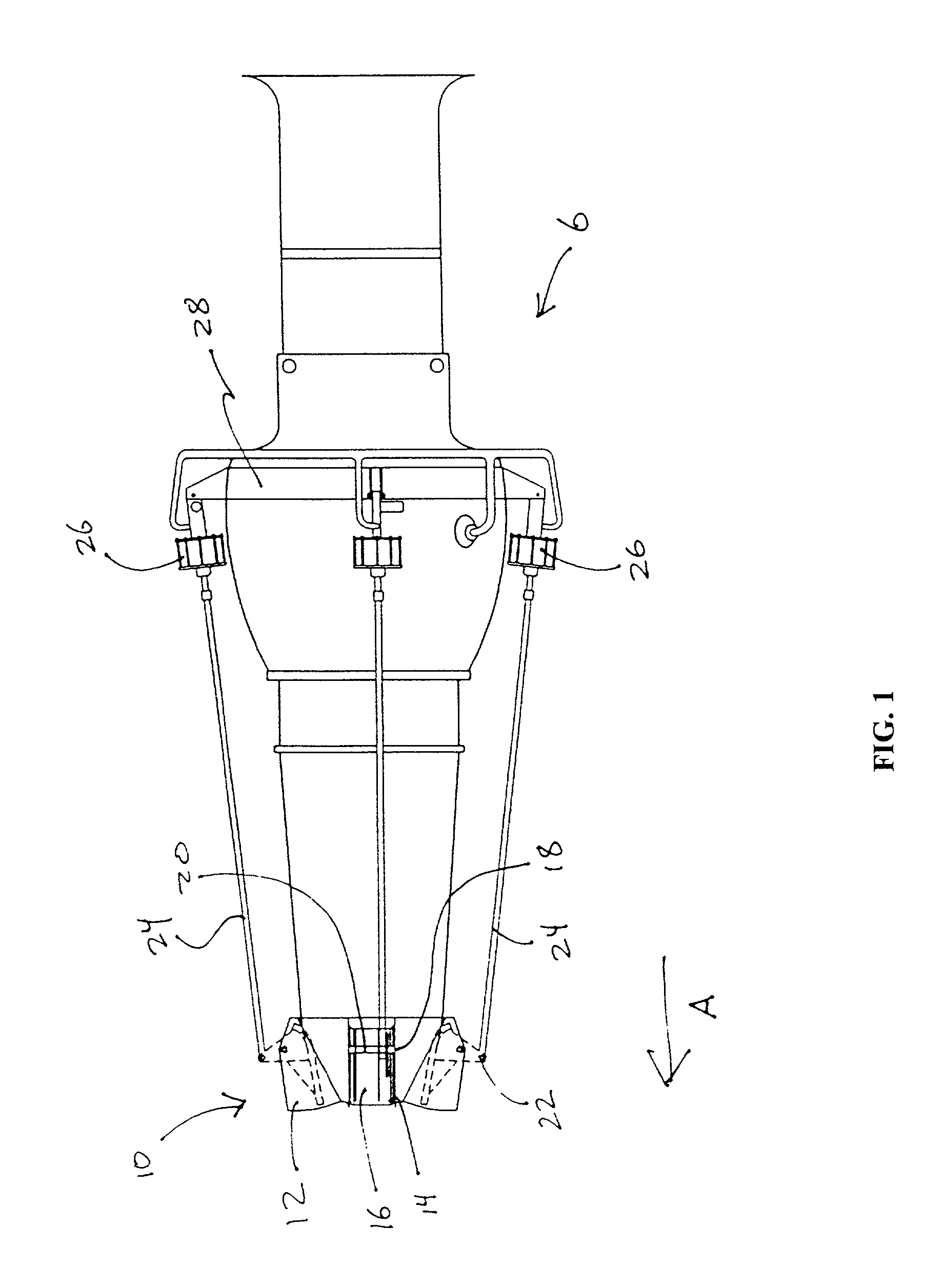
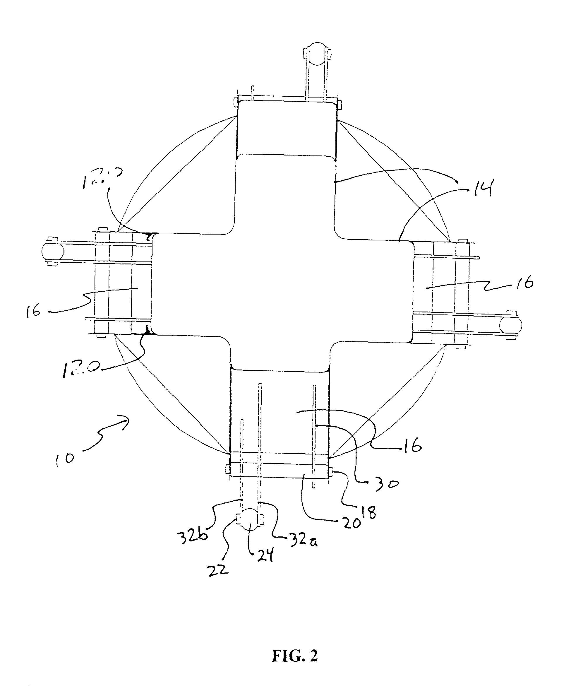
[0030] Referring now to the figures where like reference numbers indicate like elements of the present invention, FIG. 1 is a side view of a jet engine with the thrust vector controller of the present invention installed. Propulsive exhaust exits the engine at the right of the figure in the direction indicated by arrow A. Thrust vector control housing, 10, has four brackets, 12, each comprised of a pair of bracket walls, 14. Each bracket, 12, holds a vane, 16. Vanes pivot around fulcrums, 18, on fulcrum rods, 20. Vanes, 16, are rotated around fulcrum, 18, by pressure on actuation pivot, 22. Pressure is applied to actuation pivot, 22, via piston rods, 24. Piston rods, 24, are extended and retracted by pistons in cylinders, 26, which are pivotally mounted on the jet engine body by housing 28.

[0031] As best seen in FIGS. 2 and 2A, four brackets are radially disposed perpendicular to the direction of exhaust thrust, which is out of the page, towards the viewer in FIG. 2. Within each bra...


PUM


Abstract

A multi-lobed, low friction vane, thrust vector controller is disclosed. Low friction vanes are independently movable into and out of the thrust of the exhaust of a jet engine. All vanes may be used together to adjust exhaust surface area to maximize thrust and fuel efficiency in varying conditions. Vanes also move independently to impart directional force to roll, pitch and yaw traditional aircraft and hover VTOL aircraft. A bleed air pressure actuator for moving the vanes is disclosed.

Description

[0001] None[0002] None[0003] 1. Field of the Invention[0004] The present invention relates generally to efficient control of thrust vectors for jet and turbo jet engines and the actuation of their control surfaces.[0005] 2. Prior Art[0006] Thrust vector control of propulsive jet engine exhaust is desirable for a variety of applications including emergency safety steering control, reducing G force loads on aircraft control surfaces, enabling higher G turn capabilities for aircraft, optimizing engine thrust, fuel economy and thrust response time and for application in engines used in aircraft design to hover or execute vertical takeoff and landing or very short takeoff and landing. Currently available thrust vector control systems provide only coarse control. In order to provide fine control of current thrust vector controllers, auxiliary systems are necessary. These systems typically involve smaller thrusting devices remote from the main engine exhaust. Consequently, complex and expe...

Claims


Application Information

Patent Timeline
Patent Type & Authority Applications(United States)
IPC IPC(8): F02K1/00F02K1/10F02K1/12F02K1/76F15B9/10F15B15/14
CPCF02K1/002F02K1/10F02K1/12F05D2240/50F15B9/10F15B15/1485F02K1/763
Inventor PLUMPE, WILLIAM HENRY JR.
Owner GATEWAY SPACE TRANSPORT
Learn More