Motor control device
a technology of motor control and control device, which is applied in the direction of motor/generator/converter stopper, dynamo-electric gear control, motor/generator/converter stopper, etc., can solve the problems of increasing the cost of the entire system equipped with the motor, and the difficulty of detection of the phase current of two phases, so as to reduce the size of the minor axes
- Summary
- Abstract
- Description
- Claims
- Application Information
AI Technical Summary
Benefits of technology
Problems solved by technology
Method used
Image
Examples
first example
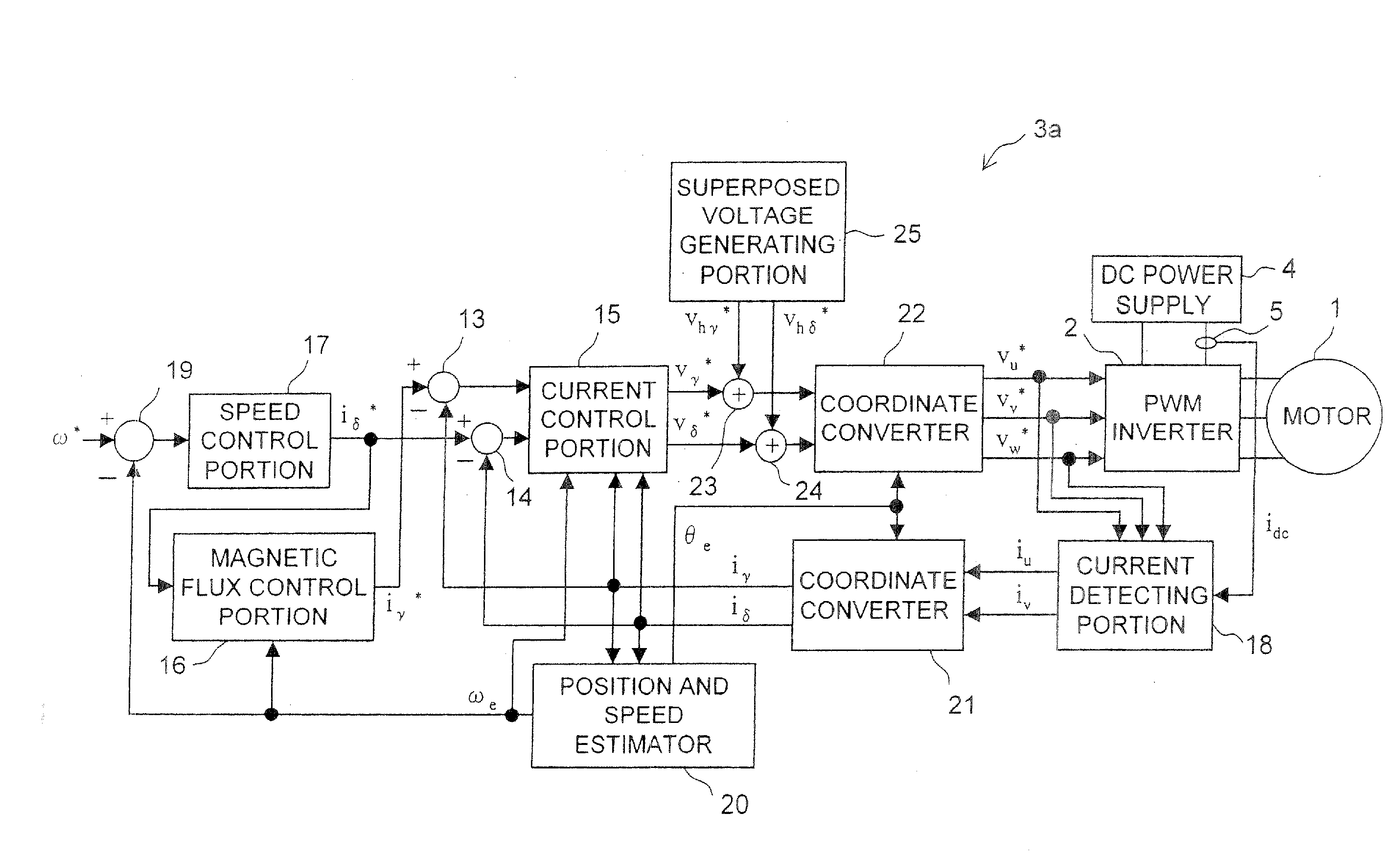
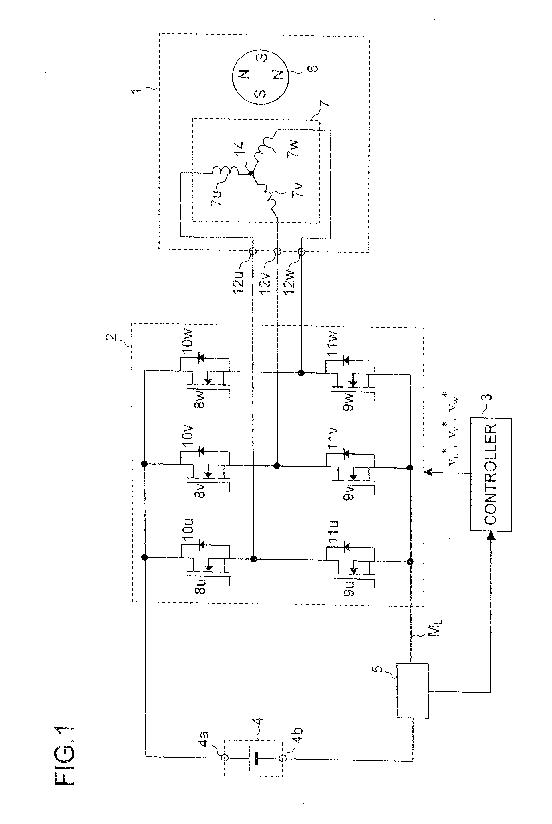
[0186]A first example will be described. FIG. 27 is a general structure block diagram of a motor driving system according to a first example. In FIG. 27, the same parts as those shown in FIG. 1 are denoted by the same reference numerals.
[0187]The motor driving system shown in FIG. 27 includes a motor 1, an inverter 2, a DC power supply 4 and a current sensor 5. It also includes a controller 3a that works as the controller 3 (the motor control device) shown in FIG. 1. The controller 3a includes subtracters 13 and 14, a current control portion 15, a magnetic flux control portion 16, a speed control portion 17, a current detecting portion 18, a subtracter 19, a position and speed estimator 20 (hereinafter referred to as “estimator 20” simply), coordinate converters 21 and 22, adders 23 and 24, and a superposed voltage generating portion 25.
[0188]As described above, the current sensor 5 detects the bus current and delivers a signal indicating a current value of the bus current. The bus ...
second example
[0204]In addition, it is possible to use a coordinate converter 22a shown in FIG. 30 instead of the coordinate converter 22 shown in FIG. 29. While the coordinate converter 22 shown in FIG. 29 performs the voltage correction at the stage of the specified voltage vector of two phases, the coordinate converter 22a shown in FIG. 30 performs the voltage correction at the stage of the three-phase voltages, which leads to the same result as the voltage correction performed by the coordinate converter 22 shown in FIG. 29. As an example for describing the coordinate converter 22a, a second example will be described. A block diagram of a general structure of a motor driving system according to the second example is similar to that of the first example (see FIG. 27), so overlapping illustrations will be omitted. However, the coordinate converter 22a shown in FIG. 30 is used in the second example as the coordinate converter 22.
[0205]The coordinate converter 22a shown in FIG. 30 includes a coor...
third example
[0207]Next, a simulation result of evaluating estimation accuracy of the motor driving system according to the first or the second example will be described as a third example. In this simulation, a period for enabling detection of the phase currents of two phases is set to a value of approximately 5 microseconds, and the threshold value Δ indicating the maximum value of the b-axis component of the voltage correction quantity is set to 10 volts for securing the period. In other words, Δ is set to 10 volts so that the time periods T1-T2 and T2-T3 shown in FIG. 4 can be ensured to be approximately 5 microseconds or longer. In addition, the DC voltage supplied from the DC power supply 4 shown in FIG. 27 is set to 280 volts, and the amplitude (Vhγ) of the superposed voltage in the γ-axis direction is fixed to 40 volts.
[0208]FIGS. 31A and 31B and FIGS. 32A and 32B show the simulation result. In graphs shown in FIGS. 31A and 31B and FIGS. 32A and 32B, the horizontal axis represents time (...
PUM
 Abstract
Description
Claims
Application Information
 - R&D
- Intellectual Property
- Life Sciences
- Materials
- Tech Scout
- Unparalleled Data Quality
- Higher Quality Content
- 60% Fewer Hallucinations
Browse by: Latest US Patents, China's latest patents, Technical Efficacy Thesaurus, Application Domain, Technology Topic, Popular Technical Reports.
© 2025 PatSnap. All rights reserved.Legal|Privacy policy|Modern Slavery Act Transparency Statement|Sitemap|About US| Contact US: help@patsnap.com


