
Permanent magnet synchronous motor speed composite control method based on continuous terminal slip form technology

A permanent magnet synchronous motor and terminal sliding mode technology, which is applied in the direction of motor generator control, electronic commutation motor control, control system, etc., can solve the problems that cannot meet the control accuracy of the system, and achieve faster convergence speed, faster convergence speed, The effect of improving the response speed

Active Publication Date: 2014-12-24
TIANJIN UNIV
View PDF5 Cites 47 Cited by
  • Summary
  • Abstract
  • Description
  • Claims
  • Application Information

AI Technical Summary

Problems solved by technology

However, on the linear sliding mode surface, the best convergence of the system is asymptotic convergence, that is, when the control object has high control precision requirements, the linear sliding mode surface often cannot meet the requirements of the system control precision

Method used


Image

  • Permanent magnet synchronous motor speed composite control method based on continuous terminal slip form technology
  • Permanent magnet synchronous motor speed composite control method based on continuous terminal slip form technology
  • Permanent magnet synchronous motor speed composite control method based on continuous terminal slip form technology

Examples


Embodiment Construction

[0040] In order to make the object, technical solution and advantages of the present invention clearer, the present invention will be further described in detail below in conjunction with the accompanying drawings and embodiments. It should be understood that the specific embodiments described here are only used to explain the present invention, not to limit the present invention. In addition, the technical features involved in the various embodiments of the present invention described below can be combined with each other as long as they do not constitute a conflict with each other.

[0041] A kind of permanent magnet synchronous motor speed composite control method based on continuous terminal sliding mode technology implemented by the present invention comprises the following steps:

[0042] Step (1): collect the three-phase current i on the stator winding a i b i c , through the Clark transformation, converted into the equivalent current i of the α and β axes in the sta...


PUM


Abstract

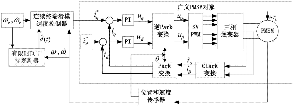
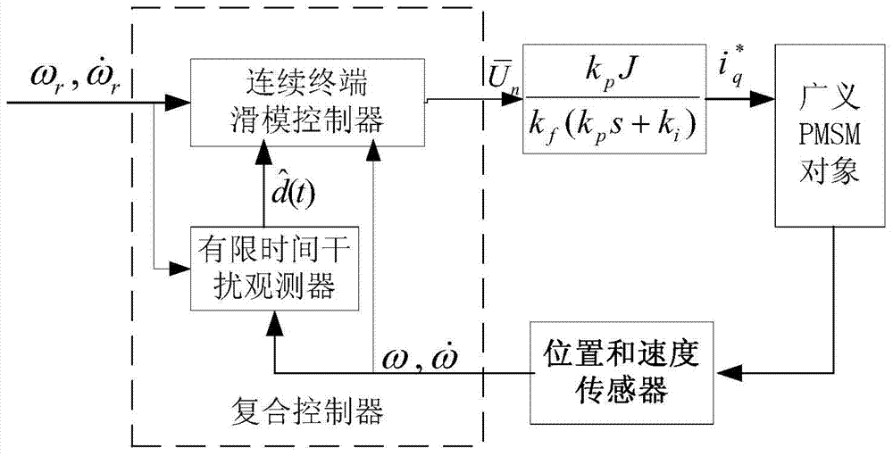
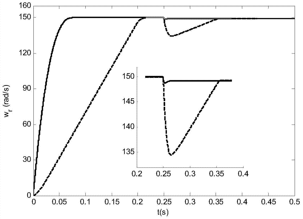
The invention discloses a permanent magnet synchronous motor speed composite control method based on a continuous terminal slip form technology. According to a vector control principle, a permanent magnet synchronous motor system is decoupled into a speed ring and a current ring which are controlled respectively. The speed ring is controlled by using the composite control method. A continuous terminal slip form controller serves as a feedback controller, the speed of a permanent magnet synchronous motor can be responded quickly in a whole adjusting process, and the problem of buffeting on slip form control is solved; a disturbance term of the speed ring is observed by a second-order limited time disturbance observer; and the second-order limited time disturbance observer which serves as a feedforward compensator has real-time observation and disturbance compensation functions. When errors are observed without disturbance, the revolving speed of the permanent magnet synchronous motor can reach reference revolving speed within a limited time; and when disturbance observation errors are bounded (img file= ' DDA0000581681490000011.TIF' wi= '35' he= '41' / ), the revolving speed of the permanent magnet synchronous motor can reach a neighborhood of the reference revolving speed (img file= 'DDA0000581681490000012. TIF' wi= '50' he= '48' / ). By the composite control method, the revolving speed of the permanent magnet synchronous motor can be adjusted effectively, and the adjusting speed and the robustness are high.

Description

technical field [0001] The invention belongs to the field of speed control of permanent magnet synchronous motors, more specifically, a continuous terminal sliding mode controller is used in the speed control system of permanent magnet synchronous motors, and a second-order finite time disturbance observer is added at the same time, so as to implement Composite control method. Background technique [0002] Due to its simple structure, reliable operation, convenient maintenance, high efficiency, no excitation loss and good speed regulation performance, the permanent magnet synchronous motor has a wide range of application prospects in the industrial field, especially in electric vehicles, aerospace and electric tools, etc. . In industrial applications, permanent magnet synchronous motors often encounter various disturbances. These disturbance sources include internal disturbances as well as external disturbances such as friction and load disturbances. At the same time, the...

Claims


Application Information

Patent Timeline
IPC IPC(8): H02P21/00
Inventor 穆朝絮徐伟贾宏杰孙长银
Owner TIANJIN UNIV
Learn More