
Sealing material for plastic liquid crystal display cells

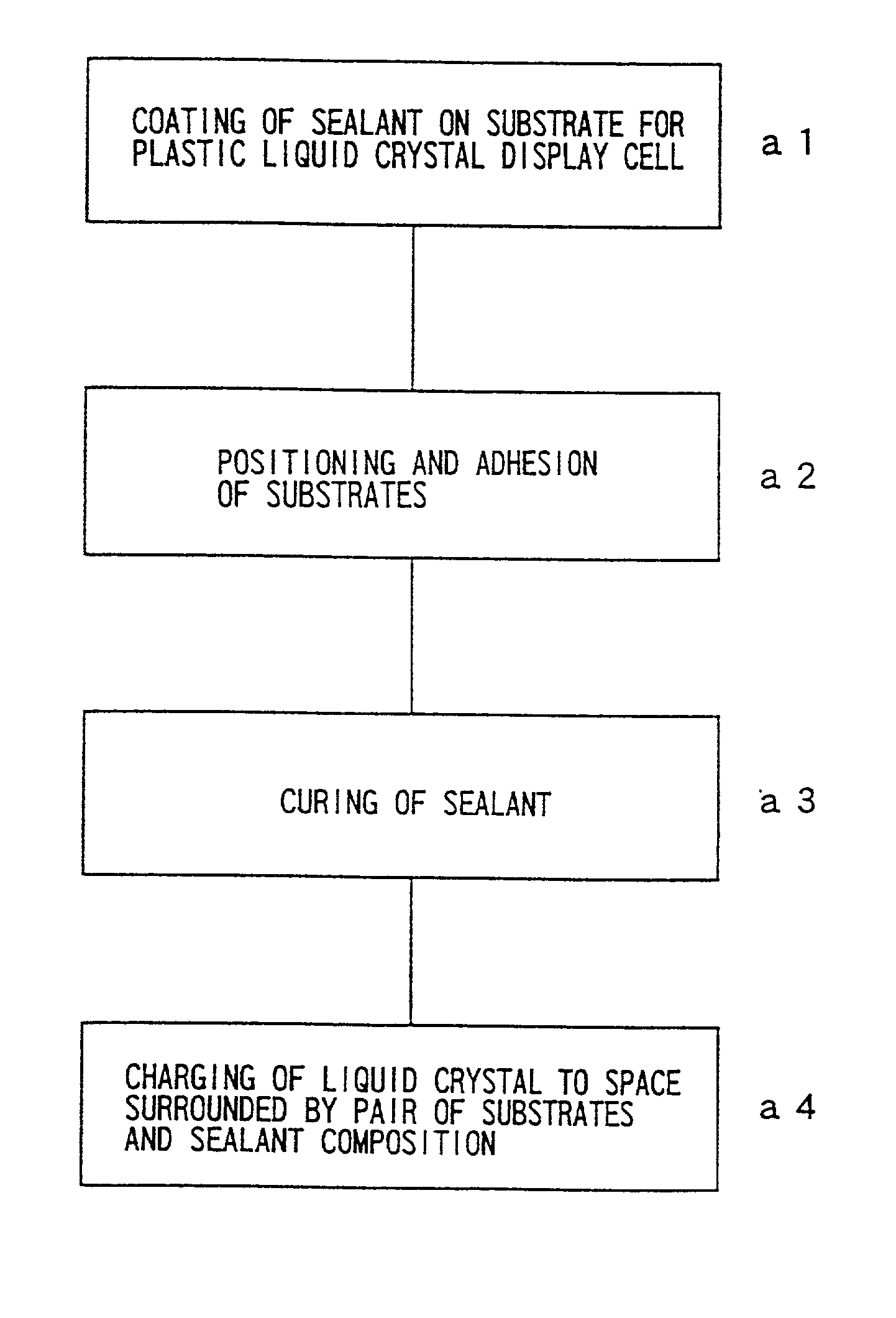
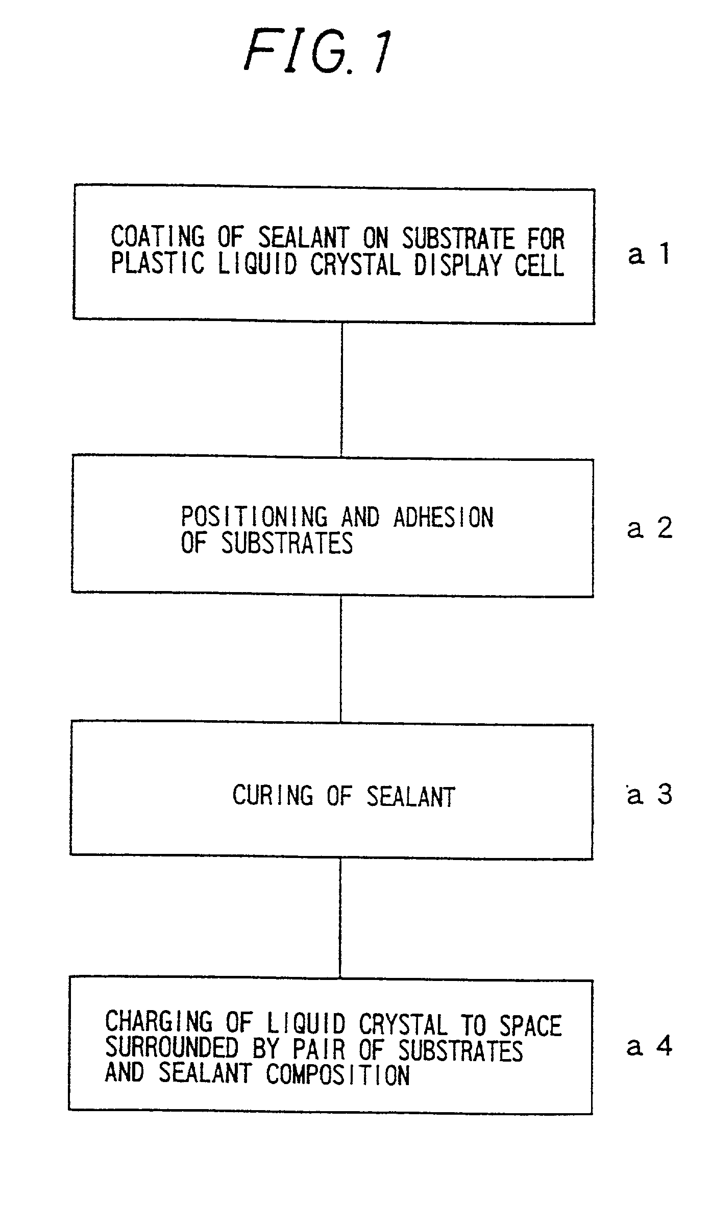
a liquid crystal display cell and adhesive technology, applied in the direction of adhesive types, instruments, transportation and packaging, etc., can solve the problems of uneven display, decreased response speed and the like, and liquid crystal display cell functional disorder

Inactive Publication Date: 2002-11-28
MITSUI CHEM INC
View PDF11 Cites 45 Cited by
  • Summary
  • Abstract
  • Description
  • Claims
  • Application Information

AI Technical Summary

Benefits of technology

[0046] According to the invention, owing to the epoxy resins used as the epoxy resin (1), a sealant composition for a plastic liquid crystal display cell having higher sealing reliability can be obtained.
[0066] According to the invention, because it is obtained by the process for producing a plastic liquid crystal display cell, stable display can be realized for a long period of time under a high temperature and high humidity environment.

Problems solved by technology

Therefore, when they are used under a high temperature and high humidity environment for a long period of time, moisture is penetrated into the interior of the plastic liquid crystal display cell through the sealant composition with the lapse of time, and as a result, functional disorder of the liquid crystal display cell, such as display unevenness, decrease in response speed and the like, occurs.

Method used


Image

  • Sealing material for plastic liquid crystal display cells
  • Sealing material for plastic liquid crystal display cells

Examples


synthesis example 1

[0411] Synthesis of epoxy resin composition (a) containing rubbery polymer fine particles (micro-crosslinking acrylic rubber fine particles, abbreviated as S1)

[0412] 500 g of Epiclon 830S and 100 g of Adeka EP4000S as the bifunctional epoxy resin, 10 g of methacrylic acid, 0.1 g of triethanolamine and 50 g of toluene were placed in a 2,000-ml four-neck flask equipped with a stirrer, a gas inlet tube, a thermometer and a condenser tube, and reaction was carried at 110.degree. C. for 5 hours under introduction of the air to introduce double bonds. 350 g of butyl acrylate, 20 g of glycidyl methacrylate, 1 g of divinylbenzene, 1 g of azobisdimethylvaleronitrile and 2 g of azobisisobutyronitrile were then added thereto, and reaction was carried out under introduction of nitrogen at 70.degree. C. for 3 hours and then at 90.degree. C. for 1 hour.

[0413] Toluene was then removed at 110.degree. C. under reduced pressure to obtain an epoxy resin composition (a).

[0414] A part of the epoxy resin...

synthesis example 2

[0416] Synthesis of epoxy resin composition (b) containing rubbery polymer fine particles (micro-crosslinking acrylic rubber fine particles, abbreviated as S2).

[0417] 604 g of Adeka EP4023S as the bifunctional epoxy resin, 6 g of methacrylic acid, 0.2 g of triethanolamine and 50 g of toluene were placed in a 2, 000-ml four-neck flask equipped with a stirrer, a gas inlet tube, a thermometer and a condenser tube, and reaction was carried at 110.degree. C. for 5 hours under introduction of the air to introduce double bonds.

[0418] 350 g of 2-ethylhexyl acrylate, 20 g of glycidyl methacrylate, 1 g of 1,6-hexanediol dimethacrylate, 1 g of azobisdimethylvaleronitrile and 2 g of azobisisobutyronitrile were then added thereto, and reaction was carried out under introduction of nitrogen at 70.degree. C. for 3 hours and then at 90.degree. C. for 1 hour.

[0419] Toluene was then removed at 110.degree. C. under reduced pressure to obtain an epoxy resin composition (b).

[0420] A part of the epoxy re...

example 1

[0422] 56 parts of the epoxy resin composition (a), 24 parts of Epiclon 830S, 14.5 parts of the bariumsulfate fine particles, 3 parts of MU-120, 2.4 parts of KBM-403, 0.09 part of the dimethylamine adduct of tolylene diisocyanate and 0.01 part of DBU octylic acid salt were preliminarily mixed in a Dalton mixer. They were then kneaded with three-roll made of ceramics until the solid raw materials became 5 .mu.m or less, and the kneaded product was subjected to a vacuum defoaming treatment to obtain a base resin liquid (P1 base resin liquid) for a two-component sealant composition for a plastic liquid crystal display cell P1.

[0423] Separately, a composition of 76 parts of pentaerythritol tetrakis(3-mercaptopropionate) and 24 parts of the barium sulfate fine particles was preliminarily mixed in a Dalton mixer. They were then kneaded with three-roll made of ceramics until the solid raw materials became 5 .mu.m or less, and the kneaded product was subjected to a vacuum defoaming treatmen...


PUM

PropertyMeasurementUnit
Temperatureaaaaaaaaaa
Linear densityaaaaaaaaaa

Abstract

An object of the invention is to provide a sealant composition for a plastic liquid crystal display cell that is capable of being applied to a sheet heat press adhesion method and of producing a plastic liquid crystal display cell having high reliability under a high temperature and high humidity environment. A two-component sealant composition for a plastic liquid crystal display cell of the invention contains the following components (1) to (6): (1) from 15 to 84% by weight of a liquid epoxy resin having from 1.7 to 6 in weight average of epoxy groups in one molecule and an ionic conductivity of an aqueous solution obtained by extraction separation by contact mixing with 10 times by weight of pure water at from 40 to 80° C. of 2 mS / m or less, (2A) from 10 to 50% by weight of a curing agent containing one or a mixture of two or more selected from (2A-1) a tetrafunctional mercapto compound or (2A-2) a modified polymercapto derivative, having an ionic conductivity of an aqueous solution obtained by extraction separation by contact mixing with 10 times by weight of pure water at from 40 to 80° C. of 0.6 mS / m or less, (3) from 0.01 to 15% by weight of a curing accelerator, (4) from 5 to 50% by weight of an inorganic filler, (5) from 0.1 to 5% by weight of a silane coupling agent, and (6) from 1 to 25% by weight of rubbery polymer fine particles having a softening temperature of 0° C. or less and an average particle diameter of primary particles of from 0.01 to 5 mum.

Description

TECHNICAL FIELD TO WHICH THE INVENTION BELONGS[0001] The present invention relates to a sealant composition for a plastic liquid crystal display cell, a process for producing a plastic liquid crystal display cell, and a plastic liquid crystal display cell.PRIOR ART[0002] In recent years, a light weight and thin liquid crystal display panel, i.e., a plastic liquid crystal display cell, is widely used as a display panel for a portable telephone. The plastic liquid crystal display cell is formed by filling a liquid crystal in a space surrounded by a pair of plastic substrates having transparent electrodes and an orientation film arranged thereon and a sealant composition for a plastic liquid crystal display cell, which is a thermosetting resin composition.[0003] The service environment of the liquid crystal display cell is becoming severer, and therefore a high quality plastic liquid crystal display cell is demanded that has impact resistance withstanding the environment and has high h...

Claims


Application Information

Patent Timeline
IPC IPC(8): C08G59/66C08K5/16C08K5/37C08K5/54C08L63/00G02F1/1333G02F1/1339
CPCC08G59/66C08K5/16C08K5/37C08K5/54C08L63/00G02F1/133305G02F1/1339Y10T428/1073C08L2666/08C09K2323/055C08K5/36C08L81/00C09D163/00C09D7/61C09D7/63C09D7/65
Inventor KITAMURA, TADASHIKONDO, HIROSHIMAEDA, SUNAO
Owner MITSUI CHEM INC
Learn More