
Small diameter low watt density immersion heating element

a heating element and small diameter technology, applied in the field of electric resistance heating elements, can solve the problems of reducing the watt density of the element, slowing the growth of scale, and not reliably eliminating scale from all areas of immersion heaters, so as to reduce the heat flux, slow down the growth of scale, and reduce the heater surface temperature

Inactive Publication Date: 2002-09-12
WATLOW POLYMER TECH
View PDF1 Cites 18 Cited by
  • Summary
  • Abstract
  • Description
  • Claims
  • Application Information

AI Technical Summary

Benefits of technology

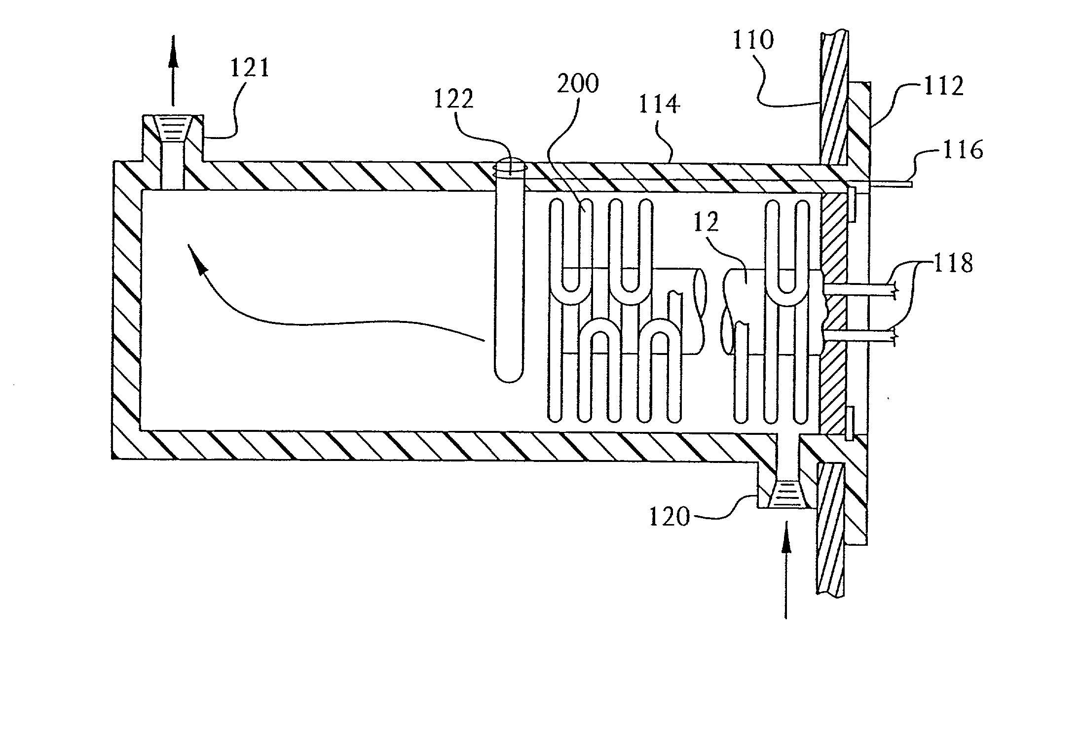
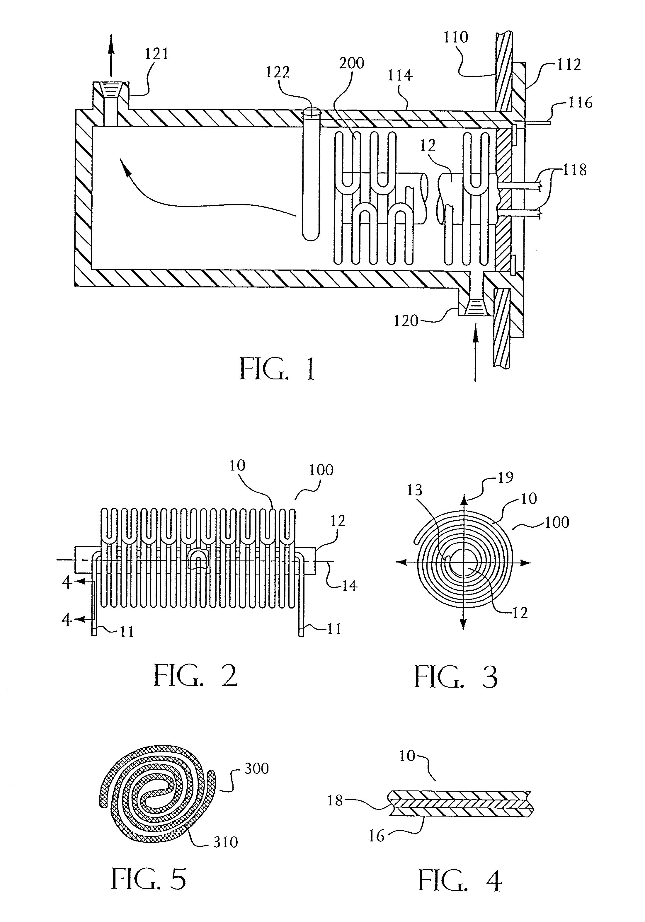
[0015] The design of the immersion heating elements in this invention substantially reduces the growth of scale in the storage container, on the element surface, or both, which consequently, also increases the life of the immersion heating element. The methods and devices of this invention employ a lower heat flux or watt density to heat fluids, which yields slower scale growth. Since calcium and calcium carbonate have a decreased solubility with increasing water temperature, reducing the watt density of the element tends to slow the growth of scale. While this is not surprising, the small active element volume ("envelope") and total wattage rating requirements of the water heater industry have formerly limited element designs to high watt density, low surface area immersion heater constructions.
[0018] The smaller diameter, low watt density immersion heating elements of this invention have been known to generate element lifetimes greater than 1,000 hours, and even exceeding 2,000 hours at total wattage outputs exceeding 1,000 watts, without element burnout or insulation breakdown. The low watt density, small diameter water heating elements of this invention can be configured to have the same total wattage rating and "envelope" size as higher watt density, larger diameter standard water heaters, yet allow for lower heater surface temperatures, lower heat flux, and slower scale growth.
[0020] It has been further discovered that, as long as water can circulate around the low watt density, small diameter heaters of this invention, i.e., the water passages are not totally blocked by scale growth, these heating elements become substantially temperature self limiting, due to further scale growth. That is, the maximum wire temperature caused by scale growth can be designed into the heater to prevent insulation breakdown or element burnout. This enables simple polymeric sheathed heating elements, or polymeric wire heaters to be employed without exceeding the melting temperature of the polymeric sheath materials, while simultaneously providing the typical power levels of about 1,000-4,500 watts required by commercial water heaters. Such total wattage ratings can be achieved within the same envelope or element volume as conventional metal sheath heaters of larger diameters, for example, those having U-shaped active element portions with diameters and watt densities of about 0.260 (200 W / in.sup.2)-0.315 (80 W / in.sup.2) inches. While providing the same envelope and total wattage as large diameter heaters, the elements of this invention provide less of a temperature gradient in the stored water, and at least 10 wt. % less scale mass, preferably at least 50 wt. % less scale mass, and as much as 96 wt. % less scale mass, in the tank.

Problems solved by technology

Since calcium and calcium carbonate have a decreased solubility with increasing water temperature, reducing the watt density of the element tends to slow the growth of scale.
While this is not surprising, the small active element volume ("envelope") and total wattage rating requirements of the water heater industry have formerly limited element designs to high watt density, low surface area immersion heater constructions.
While it has recently been believed that higher heat fluxes tend to "pop" off scale, this phenomena does not reliably eliminate scale from all areas of immersion heaters.
Discontinuities of heat flux within existing immersion heating elements has been known to cause scale to hang onto cooler areas and grow dendritically from the cooler areas to the heated areas.
Scale generation, whether it be on a metal or plastic sheath, generally leads to failure of the immersion heating element, since the resistance heating material will overcompensate to maintain fluid temperature.

Method used


Image

  • Small diameter low watt density immersion heating element
  • Small diameter low watt density immersion heating element
  • Small diameter low watt density immersion heating element

Examples


examples

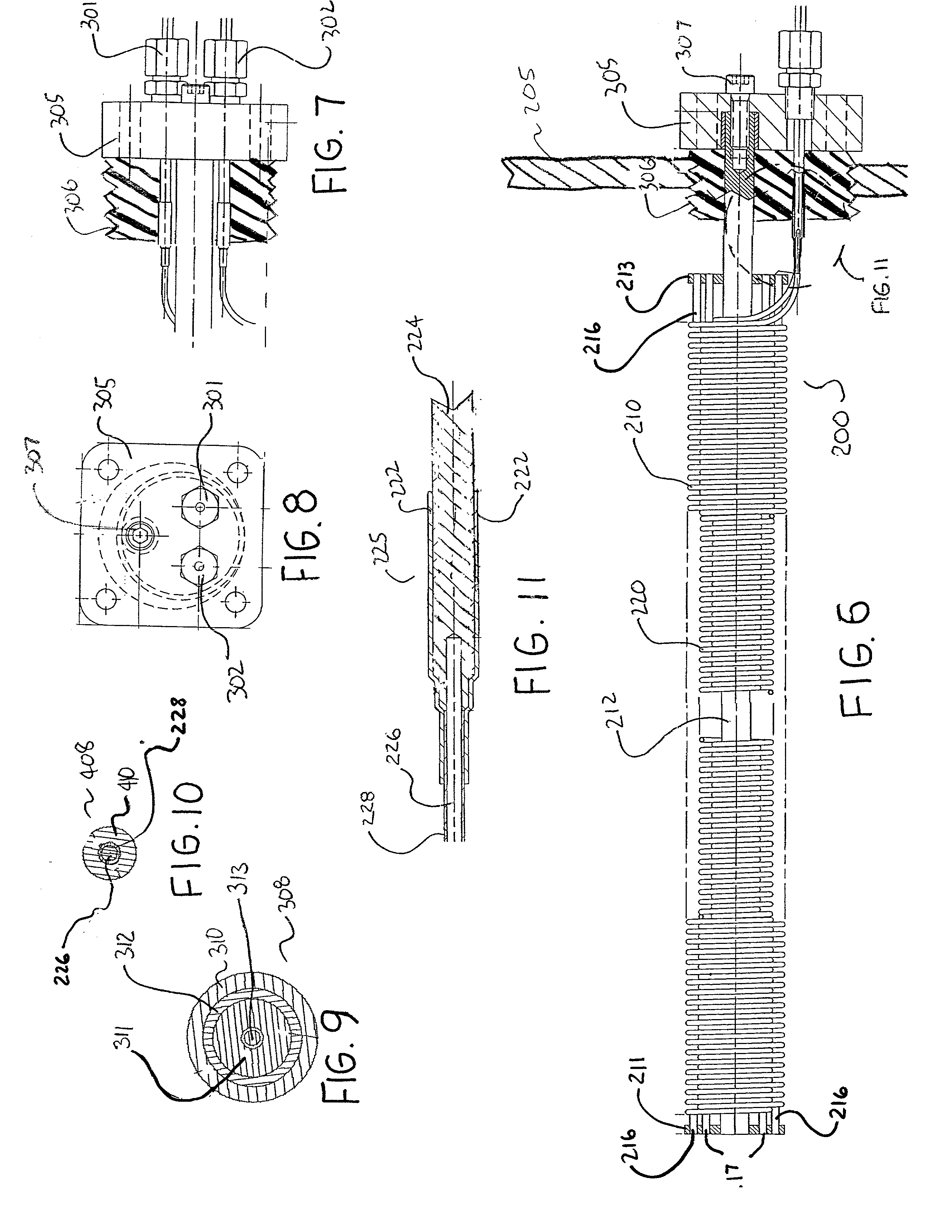
[0084] FIG. 12 graphically represents the measured temperatures along the wire, sheath and scale in relation to scale outer diameter ("O.D.", inches) and watt density (W / in.sup.2) for a 0.315" O.D., 80.67 W / in.sup.2 tubular heater 308, shown in FIG. 9. The tubular heater had a NiCr coiled wire core 313, granular MgO insulation 311, and a metal sheath 312. Scale 310 developed quickly on its surface. Also tested was a 0.069" O.D., 30 W / in.sup.2 fluorocarbon coated 0.051" dia. Chromel P (NiCr) wire heater 408, shown in FIG. 10, which also developed scale 410. Both heaters ran at the normal power density for a 4,500 watt heater.

[0085] FIG. 12 was plotted from the following data:

1 0.315 dia. tubular: Tubular Tubular Tubular Tubular Tubular Scale Wire Sheath Scale OD Scale Thickness (in.) Temp. (.degree. F.) Temp. (.degree. F.) Temp. (.degree. F.) OD (W / in.sup.2) 0 1187 235 235 80.67 0.02 1268 315 228 71.57 0.03 1305 353 226 67.75 0.05 1375 422 222 61.22 0.07 1438 485 218 55.84 0.1 1523 5...


PUM


Abstract

The present invention provides immersion heating elements, water heaters and methods for their fabrication and use. In the first embodiment of this invention, a resistance heating element is provided which includes a resistance heating material and an electrically insulating, substantially water impervious sheath disposed over the resistance heating material to form an active element portion having an envelope of about 50 in,.sup.3 a total wattage of at least 1000 W, and a watt density of no greater than 60 W / in..sup.2 Such an element has been demonstrated to substantially reduce scale reduction in water containing calcium, calcium carbonate, or both in solution.

Description

CROSS-REFERENCE TO RELATED APPLICATIONS[0001] The present application is a continuation-in-part of U.S. application Ser. No. 09 / 756,162, filed on Jan. 8, 2001, and entitled "Flexible Spirally Shaped Heating Element," and is related to U.S. application Ser. No. 09 / 275,161 filed Mar. 24, 1999, which is a continuation in part of U.S. application Ser. No. 08 / 767,156 filed on Dec. 16, 1996, now U.S. Pat. No. 5,930,459, issued on Jul. 27, 1999, which in turn is a continuation in part of U.S. application Ser. No. 365,920, filed Dec. 29, 1994, now U.S. Pat. No. 5,586,214, issued on Dec. 17, 1996, which are all hereby incorporated by reference.[0002] This application is also related to U.S. application Ser. No. 09 / 309,429, filed May 11, 1999, U.S. application Ser. No. 09 / 369,779, filed Aug. 6, 1999, and U.S. application Ser. No. 09 / 416,371, filed Oct. 13, 1999, which are also hereby incorporated by reference.FIELD OF THE INVENTION[0003] This invention relates to electric resistance heating e...

Claims


Application Information

Patent Timeline
IPC IPC(8): F24H1/10H05B3/54
CPCF24H1/102H05B3/54
Inventor TWEEDY, CLIFFORD D.VONARX, THEODORE
Owner WATLOW POLYMER TECH
Learn More