
Density enhanced, DMC, bonded permanent magnets

a technology of bonded permanent magnets and enhanced density, which is applied in the field of density enhanced, dmc, bonded permanent magnets, can solve the problems of inability to produce conventional manufacturing methods, change in composition properties, and increase in molecular weight of resin components, so as to achieve the effect of increasing the density of bonded permanent magnets and reducing the size of compressed particles

Inactive Publication Date: 2002-04-18
ELECTRON ENERGY CORP
View PDF0 Cites 20 Cited by
  • Summary
  • Abstract
  • Description
  • Claims
  • Application Information

AI Technical Summary

Benefits of technology

[0101] Another object of the present invention is to provide inorganic bonded magnets having superior magnetic properties, dimensional precision and stability at elevated use temperatures.
[0103] Still another object of the invention is to provide bonded magnets with improved strength and resistance to breakage and shock.
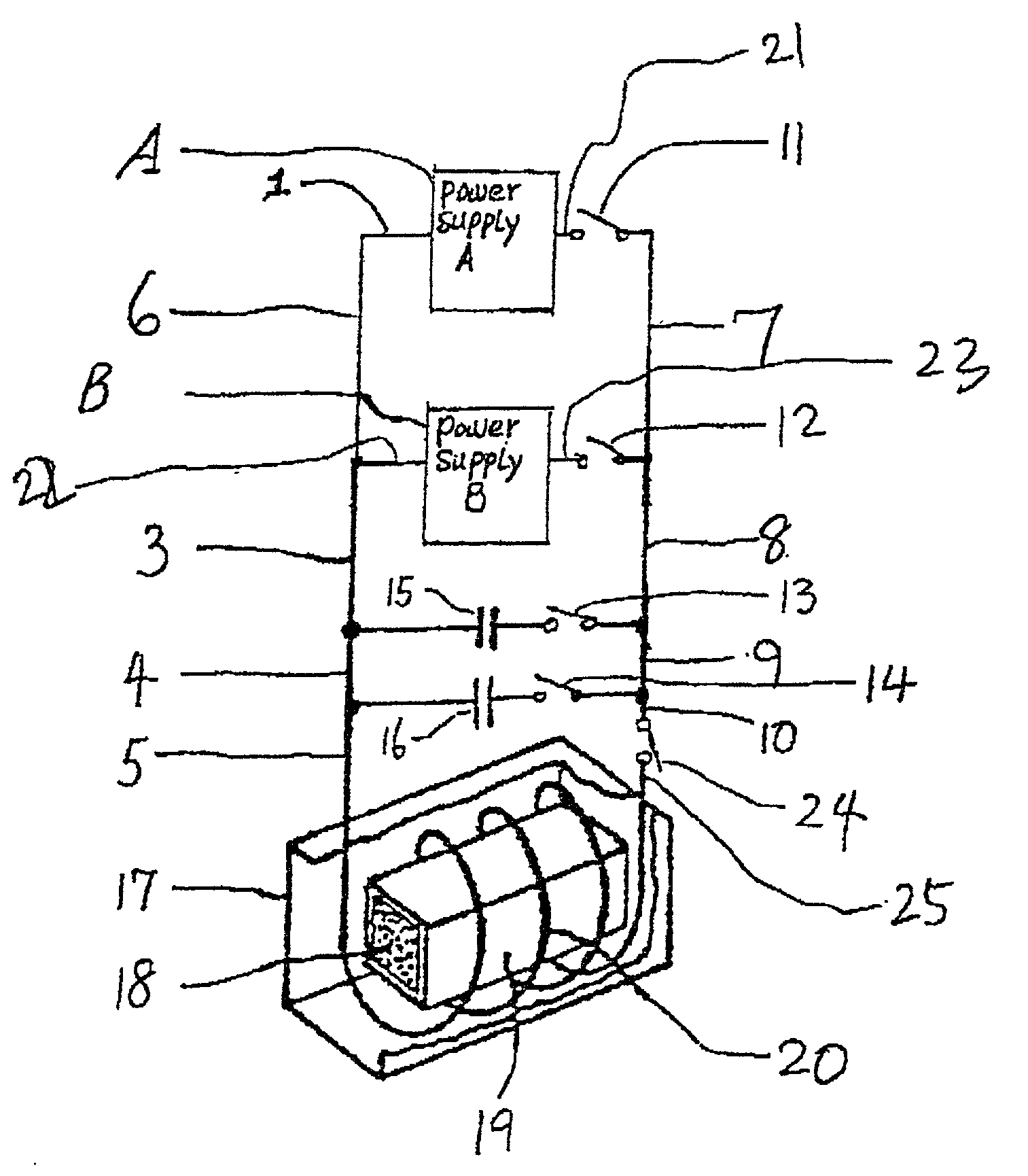
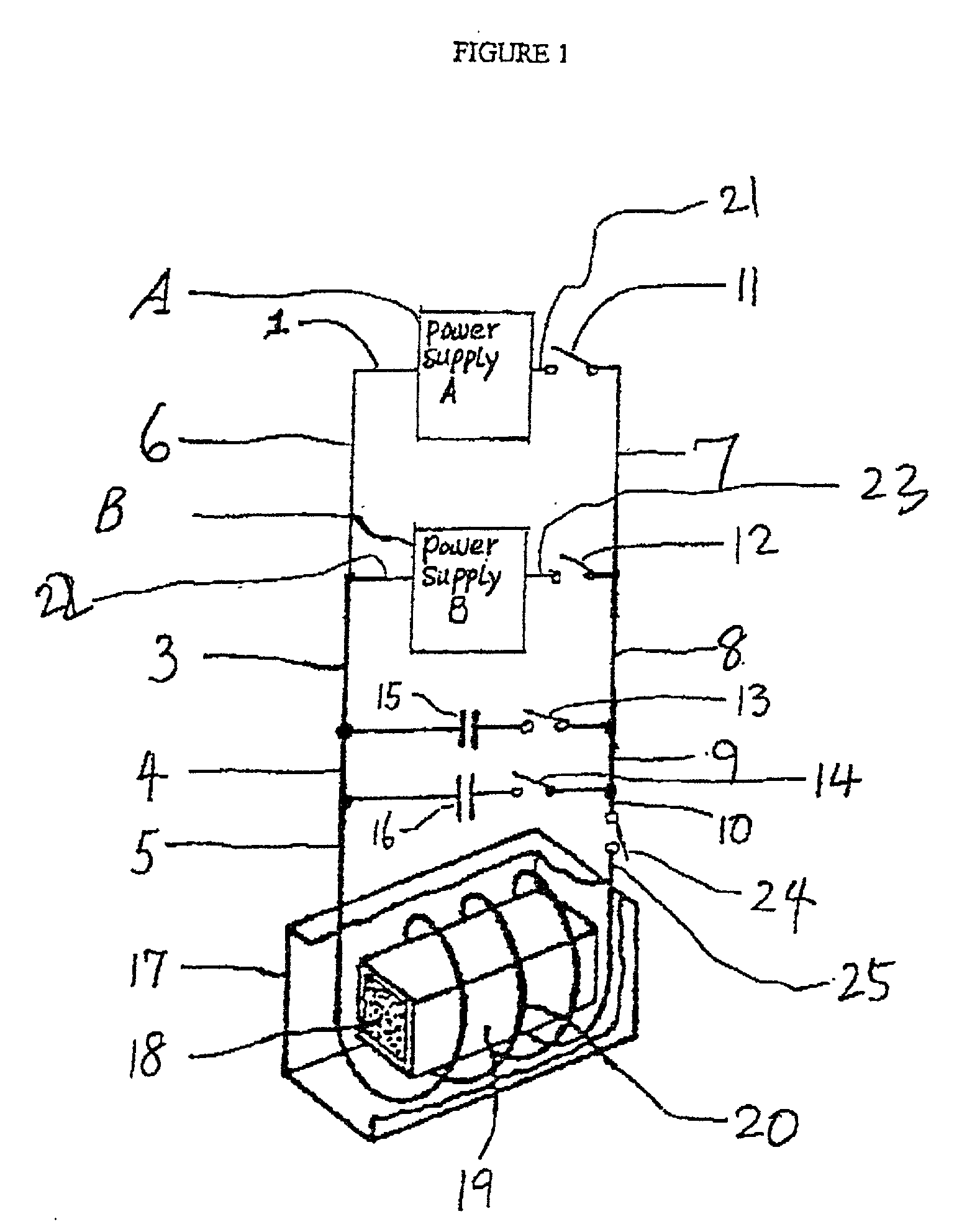
[0126] DMC achieves compaction of bonded magnets by means of at least one electromagnetic pulse, where the duration of the pulse is less than the thermal time constant of the magnet particulate. The resultant transverse electromagnetic shock wave compacts and bonds the magnetic particulate / binder mixture. The preferred magnitude of the pulsed shockwave is so chosen that it generates bonding and compaction of the magnetic particulate / binder mixture thereby maximizing density without altering the binder and thereby allowing for elevated use temperatures.

Problems solved by technology

These cannot be produced with the conventional manufacturing methods such as referenced above, i.e.,
However, the conventional rare-earth bonded magnet composition comprising a rare-earth magnet particulate and a thermoplastic resin, used in the prior art methods, particularly in injection molding and extrusion molding, has the following problems.
Specifically, since the rare-earth magnet particulate comprises a transition metal element, such as Fe or Co, when it is mixed and kneaded with a thermoplastic resin to prepare a composition which is then molded, the transition metal element catalytically generally reacts with the resin component causing an increase in molecular weight of the resin component, which results in a change in the properties of the composition, such as an increase in melt viscosity.
The above raises problems in producing stable rare-earth bonded magnets due to binder deterioration during molding, which adversely effects the magnetic properties of the molded bonded magnet.
Further, the resin used is a thermosetting resin, and there is no clear description on the properties, involved in the moldability of a magnet composition using a thermoplastic resin.
Furthermore, no particular attention is paid to a change in properties of the composition during moldings.
In actual molding, a change in properties, as described above, occurs in the course of feed of the composition into a mold of the molding machine, which makes it difficult to conduct molding.
The resultant change in properties of the composition renders the recycling difficult, unfavorably increasing the loss of material.
This incurs an increase in cost of the rare-earth bonded magnet.
Since, however, the operation is carried out in a continuous manner, holding the composition in an extruder or a die often renders the molding unacceptable.
Further, the deterioration of the composition causes a load to be applied to the machine, which often results in failure of the machine and damage to a screw and a die and a nozzle and the like of the injection-molding machine.
Further, as described above, the rare-earth magnetic particulate is sufficiently active enough to deteriorate the resin component during molding, causing the resultant magnet molding to rust when it is allowed to stand.
For this reason, the resin cannot be selected based on the moldability alone, and consequently the type and amount of the resin and the molding conditions cannot be determined from the viewpoint of the moldability alone.
Furthermore, since the resin used is a thermosetting resin, defective molded materials cannot be recycled.
This method is generally limited to the processing of small length samples.
However, as a result of the nature of varied mechanical operations involved in the two methods discussed above, consistently reproducing the many processing steps repeatedly during fabrication of long lengths of wires and tapes remains unsatisfactory.
These methods are limited in value as they are generally applicable only to production of small body sizes.
The prior art fails to teach or suggest means for efficiently producing bonded permanent magnets with increased (BH).sub.max and higher use temperatures.

Method used


Image

  • Density enhanced, DMC, bonded permanent magnets
  • Density enhanced, DMC, bonded permanent magnets
  • Density enhanced, DMC, bonded permanent magnets

Examples


example

[0190] Example M10

[0191] The bonded magnet described in Table IV above as M10 is produced as follows; the raw materials are mixed according to the formula:

(Co.sub.0.625Fe.sub.0.28Cu0.07Zr.sub.0.025).sub.8.4

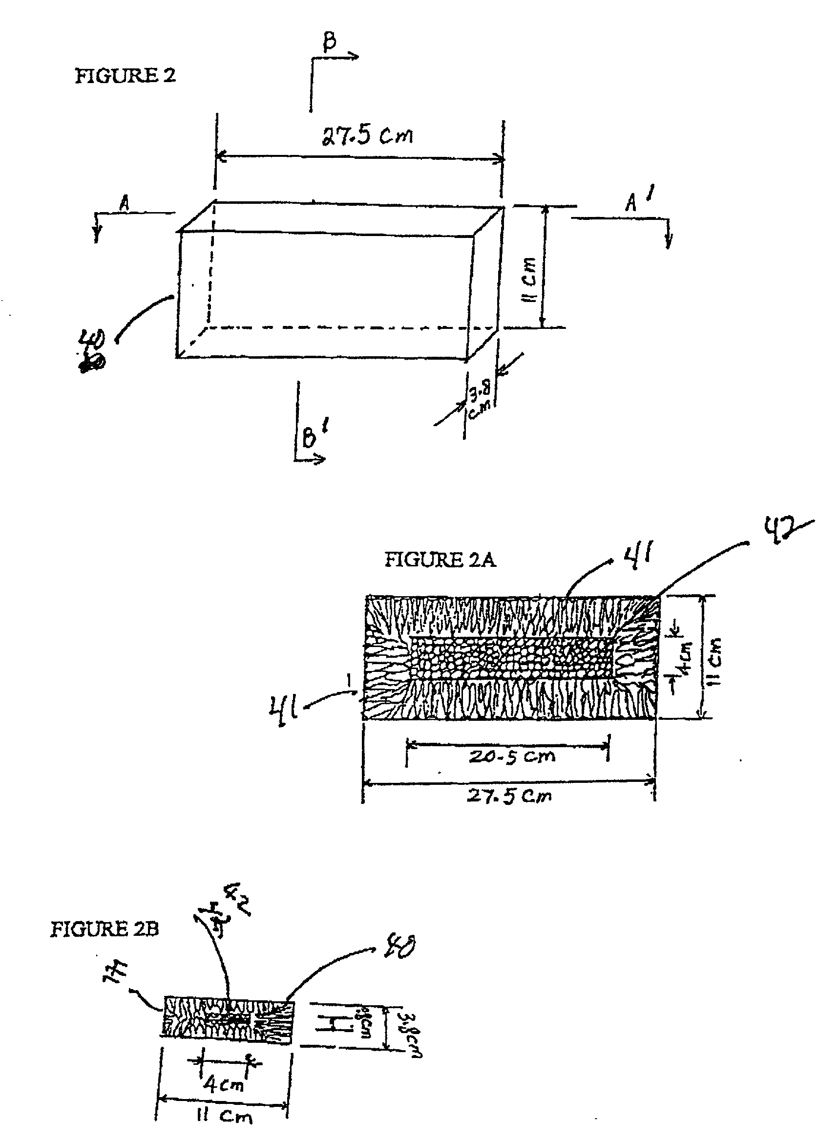
[0192] described as Example A in Table 1, and then melted in an induction-melting furnace. The melted liquid alloy is then poured into a Cu mold at a predetermined speed to produce an ingot with dimensions detailed in FIG. 2. About 90% volume percent of the desirable columnar grains within the ingot is obtained by adjusting the liquid alloy temperature, the speed of pouring liquid alloy into the Cu mold, the cooling rate of the ingot, etc. The ingot is solution-treated at 1140.degree. to 1200.degree. C. for 2 to 10 hours, and then heat-treated at 750.degree. to 850.degree. C. for 5 to 20 hours followed by slow cooling to 400.degree. C. at a rate of 1 to 1.5.degree. C. / min. Above ingot is then crushed under the protection of argon atmosphere, followed by milling to get the desired ...


PUM

PropertyMeasurementUnit
Temperatureaaaaaaaaaa
Fractionaaaaaaaaaa
Fractionaaaaaaaaaa

Abstract

A class of density enhanced, electromagnetic-pulse-compacted, bonded permanent magnets having the following properties: a. maximum energy product (BH)max up to 40% greater than that of traditional, mechanical, compacted, bonded permanent magnets, b. (BH)max up to 99% of theoretical, c. a void ratio approaching 0 volume %, d. use temperatures from room temperature up to about 550° C., and e. a structure, wherein: a mixture of permanent magnet particulates and a binder is compacted by pulsed electromagnetic forces, where each pulse has a pulse time less than the thermal time constant of the permanent magnet particulate, and said compaction is achieved without adversely affecting the binder or the structure of the permanent magnet particulate.

Description

[0001] This application claims priority from copending Provisional Application, U.S. Ser. No. 60 / 183,941, filed Feb. 22, 2000, the disclosure of which is hereby incorporated herein by reference. This application is also related to copending application Ser. No. 09 / xxx,xxx filed on even date herewith under Attorney Docket No. 4928 / 00003, which is hereby incorporated herein by reference.[0002] Permanent magnets are ubiquitous in modern societies. Devices that use permanent magnets include motors, sensors, actuators, acoustic transducers, etc. These are used in home appliances, speakers, office automation equipment, medical laboratory diagnostic test equipment, computers, disk drives, cell phones, etc.[0003] Of the many permanent magnet materials, four are predominant in use: alnico, ferrite, samarium cobalt and neodymium-iron-boron (NdFeB or "neo"). Nio was invented and commercialized in the early 1940s. Ferrite magnets, also called ceramic, were first commercialized in 1952. Samarium...

Claims


Application Information

Patent Timeline
IPC IPC(8): A61N2/00H01F1/055H01F1/08H01F13/00H01F41/02
CPCA61N2/00H01F1/0558H01F41/0273H01F13/003H01F1/083
Inventor WALMER, MARLINLIU, JINFANGWALMER, MICHAEL
Owner ELECTRON ENERGY CORP
Learn More