
Composite monolithic elements and methods for making such elements

a monolithic element and composite technology, applied in the field of composite monolithic elements and methods for making such elements, can solve the problems of low yield in the manufacturing process, relative fragility, and high cost of igniters

Inactive Publication Date: 2002-03-07
SHAFFER PETER T B +1
View PDF4 Cites 21 Cited by
  • Summary
  • Abstract
  • Description
  • Claims
  • Application Information

AI Technical Summary

Benefits of technology

[0010] In addition, composite monolithic elements containing saturation doping in accordance with the present invention can be manufactured with consistent, reproducible electrical resistivity and constant dopant concentrations. Such elements or igniters have also been found to have consistent strength, thermal expansion and thermal shock effects, and resistance to in-use degradation through oxidation and dopant diffusion.

Problems solved by technology

This type of igniter has had wide spread commercial success, but is relatively fragile and includes a number of manufacturing steps.
In addition, the yield in the manufacturing process is often less than desired.
Therefore, the igniters are very fragile.

Method used


Image

  • Composite monolithic elements and methods for making such elements
  • Composite monolithic elements and methods for making such elements
  • Composite monolithic elements and methods for making such elements

Examples


first embodiment

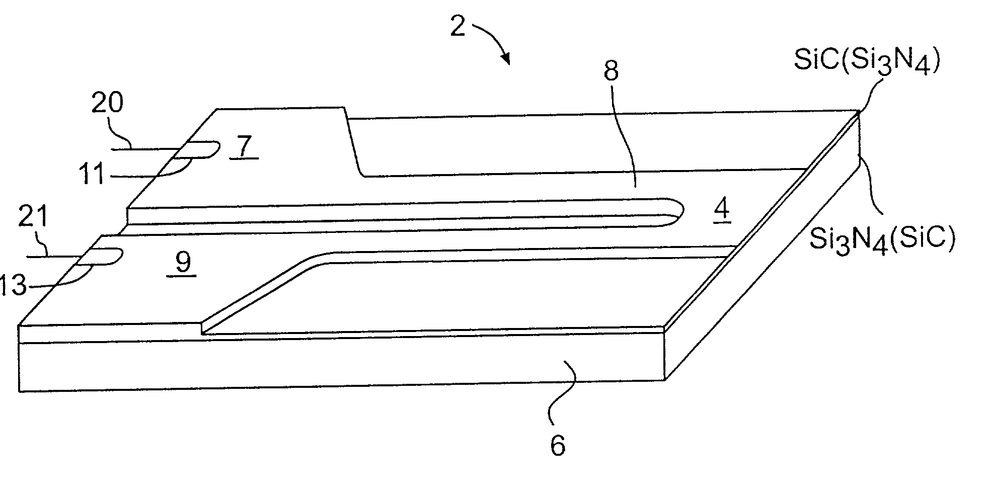
[0026] A composite monolithic heating element or igniter 2 in accordance with the invention is shown in FIG. 3. As illustrated, the igniter 2 includes a first region or layer 4 which has a first specific property. For example, in this embodiment of the invention, the first region or layer 4 act as a conductor or hot portion of the igniter 2. The igniter 2 also includes a second region or layer 6 which has a second specific property which is different than the specific property of the first layer 4. For example, the second layer 6 may act as an insulator and at the same time provides a physical support for the conductive layer 4.

[0027] An important feature of the present invention resides in the bonding together of the first and second layers 4 and 6 with a joint free bond to thereby form a mechanically continuous structure. This formation of a joint free mechanically continuous structure allows for the use of an extremely thin conductive layer 4. This feature i.e. the relatively thi...

example 1

[0045]

1 80 v / a SiC-20 v / o Si.sub.3N.sub.4 (Low Pressure Ejection Molding) Silicon Carbide (Green) FF Size 592.8 grams 1200 Grit 441.0 1600 Grit 114.0 LS-13 49.2 UF-10 84.7 UF-15 231.0 UF-25 16.7 UF-45 15.8 Total SiC 1545 Grams Si.sub.3N.sub.4 - 325 295 grams Organics Paraffin Waxes 217.5 Grams Montan Wax 3.3 Grams Surfactants / Modifier Ethylene vinyl acetate 4.4 Exxon Vistanex 5.1 Steric Acid Diethanolamicle 2.6 Oleic Acid 7.8 Chevron Oloa 1200 9.4 Polyueric Fatty Ester 2.2 Lecithin 5.9 N-Tallow 1,3 Propanedianine 2.5 Petroleum Distillate (SAE-10) 4.2 Amorphous Carbon (Calcined Petroleum Coke) 336 Grams 80 v / o Si.sub.3N.sub.4 - 20 v / o SiC (Insulator) LPEM Mix Silicon Metal - 44 Micron 670 grams - 10 Micron 390 grams Silicon Carbide (-325 mesh) 416 grams Organics Paraffin Waxes 202.5 Surfactants / Modifiers Ethylene Vinyl Acetate 4.2 Exxon Vistanex 4.9 Kantstick Z 7.3 Montan Wax 5.4 Steric Acid Diethanolanide 5.0 Oleric Acid 5.9 Steric Acid 1.5 Polymeric Fatty Ester 4.1

[0046] A process ...


PUM

PropertyMeasurementUnit
temperatureaaaaaaaaaa
aspect ratioaaaaaaaaaa
temperatureaaaaaaaaaa

Abstract

A composite monolithic element for use as a hot surface ignitor or the like includes first and second regions or layers. The first region or layer comprises a low pressure ejection molded mixture of silicon carbide and silicon nitride particles or other compatible mix which will alter processing art as a resistor. This resistor includes two cold portions and a hot portion intermediate thereof. The second region or layer also includes an ejection molded mixture of silicon carbide and silicon nitride particles or other appropriate mixture, while the second layer contains the same or similar compounds as the first, the rations of the compound differ so that after processing it acts as an insulator and as a support for the first layer. These first and second layers are bonded together to form a joint free mechanically continuous structure and densified.

Description

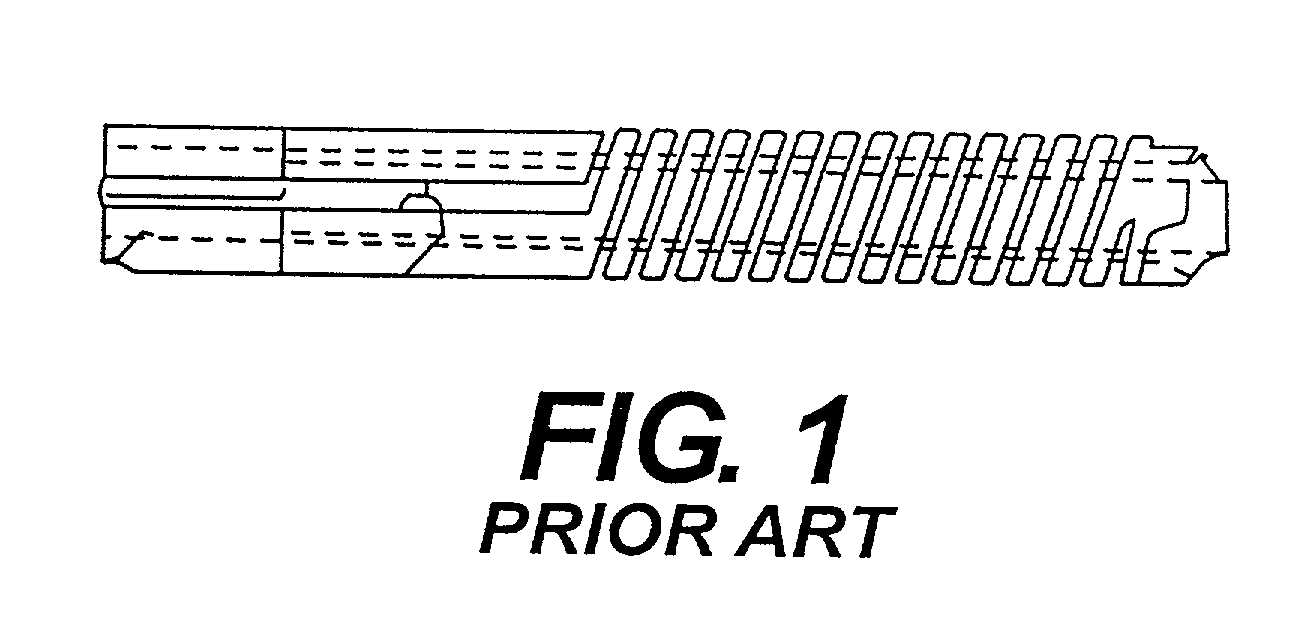
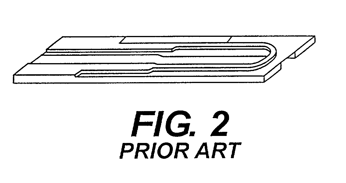
[0001] This invention relates to composite monolithic elements and more particularly to composite monolithic ceramic elements for use as or in electrical devices. The invention also relates to methods for making such elements.BACKGROUND FOR THE INVENTION[0002] The use of ceramic or refractory compositions for electrical devices such as insulators and resistors has been well known for many years. For example, igniters for fluid fuel burning systems have been described in the United States Patent of Mikulec U.S. Pat. No. 3,372,305. Such igniters, which may be referred to as spiral igniters are composed of a non-metallic resistance material such as a very dense, recrystallized silicon carbide.[0003] In the Mikulec spiral igniters, a pair of diametrically opposed slots are cut through the radial wall thickness of an elongated, hollow, tubular resistance body to form two semi-circular laterally spaced legs. A pair of closely spaced spiral slots are then cut through the wall of the body t...

Claims


Application Information

Patent Timeline
Patent Type & Authority Applications(United States)
IPC IPC(8): C04B37/00
CPCB32B18/00C04B2235/602C04B2235/6567C04B2237/365C04B2237/368C04B35/565C04B35/591C04B35/6316C04B35/632C04B2235/3826C04B2235/3873C04B2235/422C04B2235/428C04B2235/46C04B2235/5427C04B2235/5436C04B2235/5472C04B2235/6022C04B2235/9607C04B2237/58C04B2237/385C04B2237/68
Inventor SHAFFER, PETER T.B.LUNDE, MARVIN C.
Owner SHAFFER PETER T B
Learn More