
Thin, forged magnesium alloy casing and method for producing same

a magnesium alloy and casing technology, applied in the field of thin, thin, forged magnesium alloy casings, can solve the problems of difficult to cast magnesium alloys into thin products, poor plastic working of magnesium alloys, and limited magnesium alloy castings to relatively thick products

Inactive Publication Date: 2001-09-13
HITACHI METALS LTD
View PDF0 Cites 11 Cited by
  • Summary
  • Abstract
  • Description
  • Claims
  • Application Information

AI Technical Summary

Benefits of technology

[0012] Accordingly, an object of the present invention is to provide a light, thin, forged magnesium alloy casing with sharp bottom edges, corners and projections.
[0013] Another object of the present invention is to provide a light, thin, forged magnesium alloy casing with sharp bottom edges, corners and projections and substantially free from flow marks on the surface.
[0014] A further object of the present invention is to provide a method for producing such a light, thin, forged magnesium alloy casing precisely and inexpensively.
[0018] (3) When a thin magnesium alloy plate is subjected to rough forging at a limited compression ratio, the surfaces of the magnesium alloy plate in contact with the die surface do not substantially flow, only the inside of the magnesium alloy plate plastically flows laterally. As a result, good surface conditions of the magnesium alloy plate are maintained.

Problems solved by technology

The magnesium alloys are, however, much poorer in plastic working than aluminum alloys.
However, magnesium alloy castings are limited to relatively thick products, because it is extremely difficult to cast magnesium alloys into thin products.
In addition, casting defects such as pores and inclusions such as oxides, which are inevitable in casting, may be contained in the magnesium alloy castings and appear on the surface thereof.
The casting defects and the inclusions deteriorate the mechanical strength of the magnesium alloy castings, and if they appear on the surface, they adversely affect the corrosion resistance and surface appearance of the castings.
Nevertheless, the semi-solid, forming method is disadvantageous in that magnesium alloy members produced thereby are not necessarily free from defects and oxide inclusions inside and on the surface.
With defects and oxide inclusions, good surface conditions such as appearance and corrosion resistance cannot be obtained.
The deep drawing method, however, is only applicable to products having smooth surfaces, failing to provide products with projections.
In addition, a smaller die shoulder radius than the above would cause cracking in the resultant products at inner bottom edges and corners, failing to provide products with sharp bottom edges and corners.
The technology proposed by Japanese Patent Laid-Open No. 6-172949 is, however, aimed at large, thick parts such as automobile wheels, etc., not coping with difficulty in forging extremely thin products with sharp bottom edges, corners and projections.
It also requires the T.sub.6 heat treatment that takes a long period of time.
If the technology of Japanese Patent Laid-Open No. 6-172949 is applied to forged casings of magnesium alloys, the resultant forged casings would not be able to be made as thin as 1.5 mm or less with sharp bottom edges, corners and projections, because the die at 250.degree. C. cools the magnesium alloy body too low to achieve smooth plastic flow (metal flow) of magnesium alloys during the forging.

Method used


Image

  • Thin, forged magnesium alloy casing and method for producing same
  • Thin, forged magnesium alloy casing and method for producing same
  • Thin, forged magnesium alloy casing and method for producing same

Examples


example 1

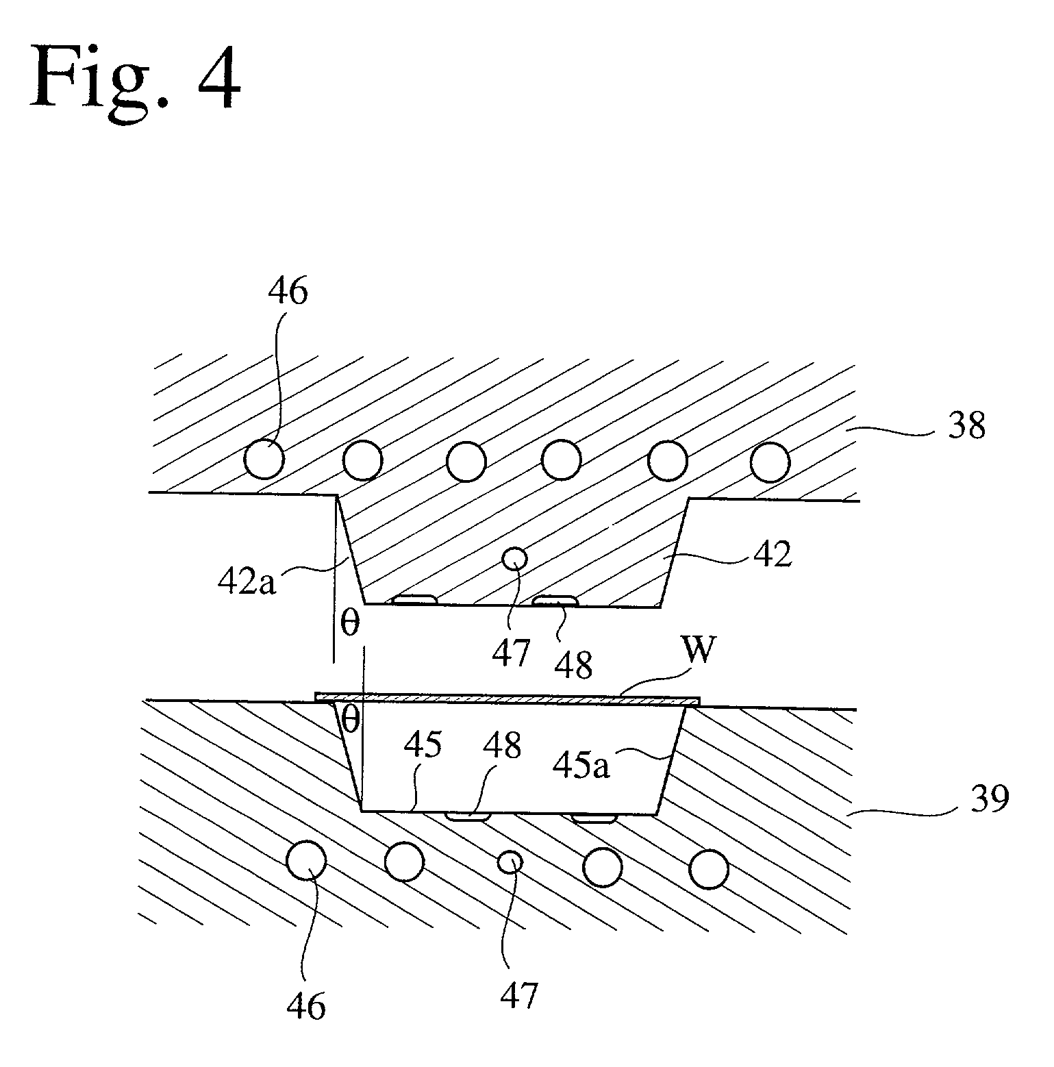
[0091] Ten round magnesium alloy rods (AZ31) of 30-40 mm in diameter and 10-40 mm in length were preheated at 500.degree. C. and placed in a first forging die shown in FIG. 4, which were coated with a graphite lubricant and heated at 400.degree. C. The first forging step was carried out under the conditions of a compression speed of 200 mm / sec. and a compression pressure of 20 tons / cm.sup.2 to form intermediate forged products having a thickness of 0.8-1.0 mm in a flat, thin plate area.

[0092] Next, each intermediate forged product was heated at 400.degree. C. and subjected to a second forging step under the conditions of a die temperature of 350.degree. C., a compression speed of 50 mm / sec. and a compression pressure of 10 tons / cm.sup.2 to form a box-shaped, thin forged casing. After trimming sidewalls, removal of the lubricant and polishing were carried out. The resultant thin forged casing had a size as follows:

[0093] Bottom: 80 mm.times.80 mm,

[0094] Sidewall: 5 mm (height),

[0095]...

example 2

[0103] This EXAMPLE used a first forging die consisting of a lower die block having a cavity whose inner bottom edges had a radius of curvature of 0.6 mm and an upper die block having a punch portion whose shoulder had a radius of curvature of 2.5 mm, and a second forging die consisting of a lower die block having a cavity whose inner bottom edges had a radius of curvature of 0.6 mm, and an upper die block having a punch portion whose shoulder had a radius of curvature of 0.7 mm.

[0104] A thin, flat magnesium alloy plate (AZ31) of 100 mm.times.100 mm.times.1.0 mm, which had lines 110 in a checkerboard pattern as shown in FIG. 11, was uniformly preheated at 450.degree. C. in an electric furnace filled with an argon gas and placed in a first forging die heated at 400.degree. C. The first forging step was carried out for rough forging under the conditions of a compression speed of 200 mm / sec., a compression pressure of 10 tons / cm.sup.2 and a compression ratio of 30%. The resultant box-s...

example 3

[0111] This EXAMPLE used a first forging die consisting of a lower die block having a cavity whose inner bottom edges had a radius of curvature of 0.8 mm and an upper die block having a punch portion whose shoulder had a radius of curvature of 3.5 mm.

[0112] A thin, flat magnesium alloy plate (Az31) of 55 mm.times.160 mm.times.1.5 mm was uniformly preheated at a temperature ranging from 200.degree. C. to 550.degree. C. in an electric furnace filled with an argon gas and placed in a first forging die heated at 400.degree. C. The first forging step was carried out for rough forging under the conditions of a compression speed of 200 mm / sec., a compression pressure of 10 tons / cm.sup.2 and a compression ratio of 20 %.

[0113] At preheating temperatures of the magnesium alloy plates between 350.degree. C. and 500.degree. C., box-shaped, intermediate forged products each having a bottom of 50 mm.times.155 mm, sidewalls of 6 mm in effective height, and a thickness of 1.2 mm in a flat plate por...


PUM

PropertyMeasurementUnit
compression ratioaaaaaaaaaa
thicknessaaaaaaaaaa
compression ratioaaaaaaaaaa

Abstract

A thin, forged magnesium alloy casing is integrally constituted by a thin plate with projections on either or both surfaces, and the thin plate is as thin as about 1.5 mm or less. The thin forged casing can be produced by (a) carrying out a first forging step for roughly forging a magnesium alloy plate to form an intermediate forged product under the conditions of a preheating temperature of the magnesium alloy plate of 350-500° C., a die temperature of 350-450° C., a compression pressure of 3-30 tons / cm2, a compressing speed of 10-500 mm / sec. and a compression ratio of 75% or less; and (b) carrying out a second forging step for precisely forging the intermediate forged product under the conditions of a preheating temperature of the intermediate forged product of 300-500° C., a die temperature of 300-400° C., a compression pressure of 1-20 tons / cm2, a compressing speed of 1-200 mm / sec., and a compression ratio of 30% or less.

Description

[0001] The present invention relates to a thin, forged magnesium alloy casing suitable as light, strong casings for small electronic appliances and media and a method for producing such a thin forged casing.[0002] Because magnesium has the smallest specific gravity of 1.8 among metal materials put into practical use at present, magnesium alloys are finding wide expectations and applications as light, strong materials alternative to aluminum having a specific gravity of 2.7 and it alloys. Magnesium alloys may be used for parts of aircraft and spacecraft, land transportation equipment, cargo equipment, industrial machines and tools, electronic equipment, telecommunications equipment, agricultural machines, mining machines, office equipment, optical equipment, sports gears, etc.[0003] The magnesium alloys are, however, much poorer in plastic working than aluminum alloys. Accordingly, the magnesium alloys are usually provided as die-castings at present. To improve castability and mechan...

Claims


Application Information

Patent Timeline
Patent Type & Authority Applications(United States)
IPC IPC(8): B21J5/02B21K21/02H05K5/02
CPCB21J5/02B21K21/02B21K23/00H05K5/02Y10T428/12389Y10T428/12382Y10T428/12993Y10T428/12361Y10T428/12375Y10T428/31681B21K21/04C22C23/02B21J5/12B05D5/00
Inventor SEKI, ISAOHAMA, SHIGEOTANIIKE, SHIGEHIROWATANABE, FUKASHIKAKIZAKI, MASAHIKOSEKI, SHINJI
Owner HITACHI METALS LTD
Learn More