Techniques for generation of high brightness beams using a ridge waveguide

a technology of ridge waveguide and beam generation, applied in the field of light detection and ranging, can solve the problems of signal degradation, reducing coupling efficiency, and severely degrading of target signals from distant objects

Active Publication Date: 2022-08-09
AEVA INC
View PDF4 Cites 0 Cited by
  • Summary
  • Abstract
  • Description
  • Claims
  • Application Information

AI Technical Summary

Benefits of technology

[0006]Example implementations of the present disclosure are configured to simultaneously measure range and velocity, using coherent detection, and have the added benefit of immunity to crosstalk from other LIDAR systems. Other implementations may be used with incoherent systems to improve, range, frame rate, or detection. Example implementations minimize optical losses in the beam's return path, thereby increasing the system's measurement range. Additionally, by using nondegenerate optical sources, example implementations can leverage mature wavelength division multiplexing (WDM) techniques often used in integrated silicon photonics, a desired platform due to its compactness and relative stability in varying environmental conditions.
[0007]A conventional frequency-modulated continuous-wave (FMCW) LIDAR system relies on scanning an optical beam, such as a laser beam, or multiple optical beams over a desired field of view (FOV) to map target space in three dimensions (3D) and in time. To guide the optical beam, a conventional LIDAR system may utilize one or more waveguides. Each conventional waveguide may include a first cladding layer (also referred to as a “p-cladding layer” hereafter) and a second cladding layer (also referred to as an “n-cladding layer” hereafter) that have relatively similar thicknesses and constant refractive indexes. While a conventional waveguide may be suitable for guiding the optical beam, the design of the conventional waveguide may be improved to increase the performance of the conventional FMCW LIDAR system.
[0010]Use of the waveguide may provide for an improved LIDAR system. The range of refractive indexes of the n-cladding layer may pull and expand the optical mode of the optical beam into the n-cladding layer from the p-cladding layer. This may result in an increase in the saturation power of the optical beam because the optical confinement factor and differential gain are significantly reduced. This may also result in improved coupling efficiency by expanding the beam profile vertically to match another waveguide of the LIDAR system, improved efficiency of the optical beam, and reduce amplitude and phase noises experienced by the optical beam, all of which improve the performance of the LIDAR system.

Problems solved by technology

When using mirrors with a high angular velocity and single-mode fiber-based detection, a target signal from distant objects can be severely degraded.
Signal degradation is often due to the difference in angular position of the scanner mirror from the launch time of the optical signal (pulsed or frequency swept) to the collection time of the same signal from a distant scattering target.
This slight angular change causes a walk-off of the target signal at the fiber tip decreasing the coupling efficiency, which manifests itself as a weaker signal detection.
Such degradation becomes more severe as the fiber diameter decreases or as the mirrors' angular velocity increases.
Historically, FM LIDAR systems suffer from significant losses in the beam's return path; thus, such systems, which are often quite bulky, require a higher average beam output power to measure distances comparable to time-of-flight (TOF) LIDAR systems.
However, the range is limited by the operating distance for eye-safe output powers.

Method used


Image

  • Techniques for generation of high brightness beams using a ridge waveguide
  • Techniques for generation of high brightness beams using a ridge waveguide
  • Techniques for generation of high brightness beams using a ridge waveguide

Examples


Embodiment Construction

[0024]According to some embodiments, the described LIDAR system described herein may be implemented in any sensing market, such as, but not limited to, transportation, manufacturing, metrology, medical, virtual reality, augmented reality, and security systems. According to some embodiments, the described LIDAR system is implemented as part of a front-end of frequency modulated continuous-wave (FMCW) device that assists with spatial awareness for automated driver assist systems, or self-driving vehicles.

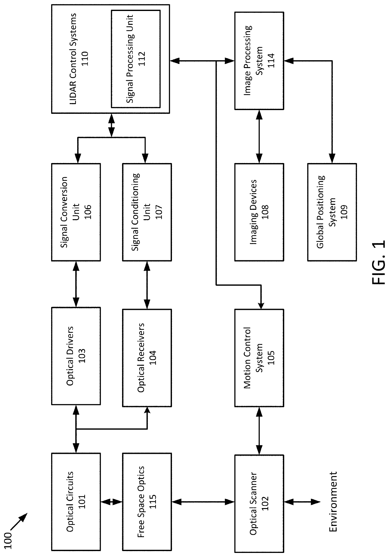
[0025]FIG. 1 illustrates a LIDAR system 100 according to example implementations of the present disclosure. The LIDAR system 100 includes one or more of each of a number of components, but may include fewer or additional components than shown in FIG. 1. One or more of the components depicted in FIG. 1 can be implemented on a photonics chip, according to some embodiments. The optical circuits 101 may include a combination of active optical components and passive optical components. Act...


PUM

PropertyMeasurementUnit
beat frequencyaaaaaaaaaa
refractive indexaaaaaaaaaa

Abstract

A light detection and ranging apparatus (LIDAR) includes an optical source to generate an optical beam and one or more waveguides to steer the optical beam. The one or more waveguides include a first cladding layer having a first refractive index and a second cladding layer disposed below the first cladding layer, the second cladding layer having second refractive indexes including a range of different refractive indexes, wherein the range of different refractive indexes is greater than the first refractive index of the first cladding layer.

Description

RELATED APPLICATION[0001]This application claims priority and the benefit of U.S. patent application Ser. No. 17 / 188,072 filed Mar. 1, 2021, the entire contents of which are incorporated herein by reference.TECHNICAL FIELD[0002]The present disclosure relates generally to light detection and ranging (LIDAR) that provides simultaneous measurement of range and velocity across two dimensions.BACKGROUND[0003]Fast-scanning mirrors are the primary components used to illuminate a scene in most conventional LIDAR systems. One mirror typically scans quickly along the X direction (azimuth), while another mirror scans slowly along the Y direction (elevation). Light emission and detection from target reflections are done coaxially, typically via a single-mode fiber. A 3D point cloud can be established when point-wise detected range information is combined with angular position feedback from the scanning mirrors.[0004]To achieve higher frame rates, the mirror's angular velocity is increased, espe...

Claims


Application Information

Patent Timeline
Patent Type & Authority Patents(United States)
IPC IPC(8): G01S7/481G01S17/32G02B6/42
CPCG01S7/4814G01S7/4817G01S17/32G02B6/4202G02B6/122G02B6/1228G02B2006/12097G02B2006/12095G01S7/4818G01S17/34
Inventor ALALUSI, MAZINSRINIVASAN, PRADEEPMASUDA, KEVIN
Owner AEVA INC
Why Eureka
Try Eureka