
Precursor structure of perpendicularly magnetized film, perpendicularly magnetized film structure and method for manufacturing the same, perpendicular magnetization-type magnetic tunnel junction film in which said structure is used and method for manufacturing the same, and perpendicular magnetization-type magnetic tunnel junction element in which said structure or magnetic tunnel junction film is used

a perpendicular magnetized film, perpendicular magnetized film technology, applied in the direction of magnets, instruments, substrate/intermediate layers, etc., can solve the problems of reduced magnetic anisotropy, complex manufacturing process of perpendicular magnetized film structure using mgal, etc., to achieve greater perpendicular magnetic anisotropy (pma), improve heat resistance, and high pma

Active Publication Date: 2022-06-28
NAT INST FOR MATERIALS SCI
View PDF10 Cites 0 Cited by
  • Summary
  • Abstract
  • Description
  • Claims
  • Application Information

AI Technical Summary

Benefits of technology

This approach results in a perpendicularly magnetized film with enhanced magnetic anisotropy and heat resistance, minimizing lattice mismatch effects and allowing for adjustable saturation magnetization and magnetic anisotropy energy, leading to improved performance in magnetic tunnel junctions.

Problems solved by technology

However, there is a lattice mismatch of about several percent between MgO and these soft magnetic materials and it is necessary to obtain all the layers in ultrathin film shapes having about nanometer thicknesses, and thus the decrease in magnetic anisotropy due to the effect of crystal distortion occurring at the interface is not ignored.
However, the magnetic anisotropy is greatly affected by the electronic state at the interface, it is thus necessary to realize a high crystallinity and controlled interface structure, and there is a problem that the manufacturing process of the perpendicularly magnetized film structure using MgAl2O4 is complicated.
For example, the combination of a Co2FeAl alloy layer and MgAl2O4 (Patent Literature 4) has a problem that the manufacturing process of the perpendicularly magnetized film structure is complicated.

Method used


Image

  • Precursor structure of perpendicularly magnetized film, perpendicularly magnetized film structure and method for manufacturing the same, perpendicular magnetization-type magnetic tunnel junction film in which said structure is used and method for manufacturing the same, and perpendicular magnetization-type magnetic tunnel junction element in which said structure or magnetic tunnel junction film is used
  • Precursor structure of perpendicularly magnetized film, perpendicularly magnetized film structure and method for manufacturing the same, perpendicular magnetization-type magnetic tunnel junction film in which said structure is used and method for manufacturing the same, and perpendicular magnetization-type magnetic tunnel junction element in which said structure or magnetic tunnel junction film is used
  • Precursor structure of perpendicularly magnetized film, perpendicularly magnetized film structure and method for manufacturing the same, perpendicular magnetization-type magnetic tunnel junction film in which said structure is used and method for manufacturing the same, and perpendicular magnetization-type magnetic tunnel junction element in which said structure or magnetic tunnel junction film is used

Examples


example 1

[0084](C) Characteristics

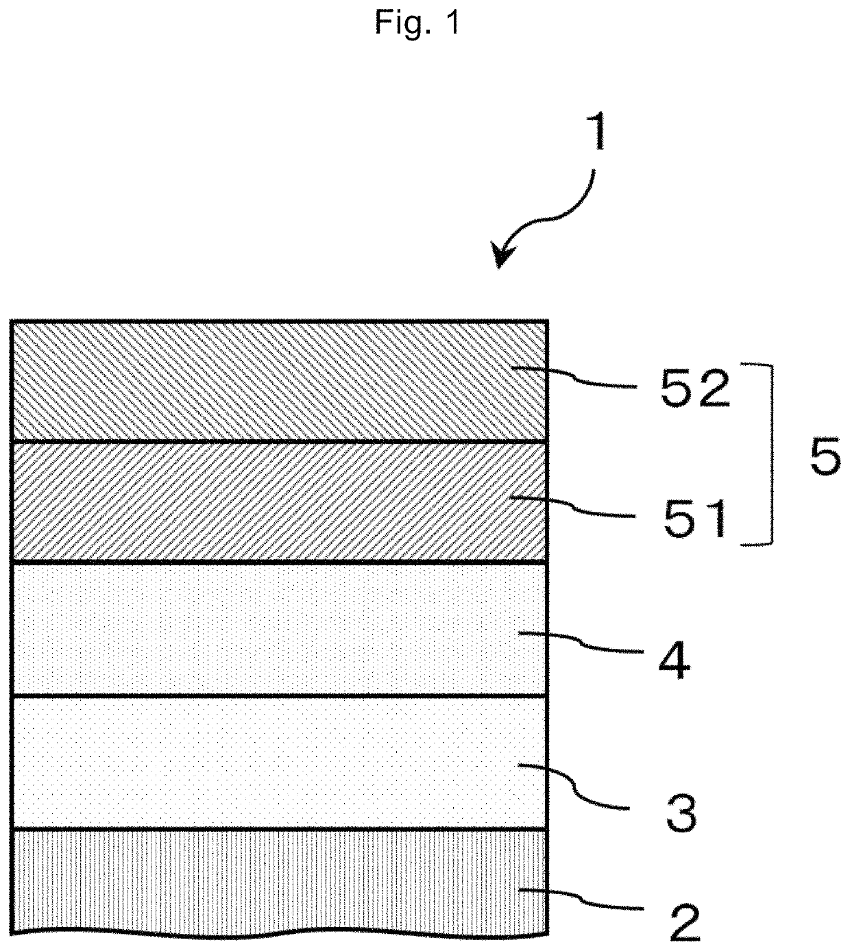
[0085]Next, the perpendicularly magnetized film of the present embodiment will be explained in the following Examples with reference to FIG. 6 and FIG. 7.

[0086]As the perpendicularly magnetized film structure, an example in which a multilayer film having a structure of MgO (001) single crystal substrate / Cr (40 nm) / iron-based alloy layer Fe—Al (tFeAl) / Mg (0.2 nm) / Mg—Al (tMgAl)-indirect plasma oxidation / Ru (2 nm) is formed by sputter deposition and plasma oxidation will be described. Here, tFeAl is the iron-based alloy layer (Fe—Al) film thickness and tMgAl is the Mg—Al film thickness. The MgO single crystal substrate was washed with an organic solvent and ultrapure water, then introduced into a vacuum chamber, and heated at 600° C. to obtain a clean crystal plane. Thereafter, the substrate was cooled to room temperature, and then the respective layers were formed using a 2-inch magnetron sputtering apparatus. For the formation of Fe—Al layer, simultaneous spu...

example 2

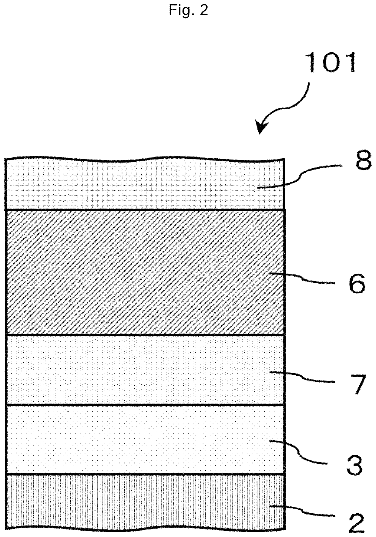
[0090]Next, with regard to the perpendicularly magnetized film of the present embodiment, an example is described in which an Fe100-xAlx layer having a film thickness of 1 nm is used as the iron-based alloy layer 4 of the perpendicularly magnetized film structure of FIG. 2. The atomic ratios used in this example are x=11.0, 19.6, and 27.9 (composition in Example 1: Fe72Al28). With regard to the second alloy film 52, the film thickness was 0.7 nm and the Mg—Al composition was Mg40Al60. By the indirect plasma oxidation method, the first metal layer Mg and the second alloy film 52 are oxidized into a Mg—Al—O layer, and MgAl2O4 is preferably adopted as the degree of oxidation.

[0091]FIG. 10 is a graph illustrating the dependency of the magnitude Ku of perpendicular magnetic anisotropy on the annealing heat treatment temperature Tex. At high Tex (=450° C.), a high Ku is realized at a composition of x=19.6% and the heat resistance is significantly favorable. In contrast, at the composition...

example 3

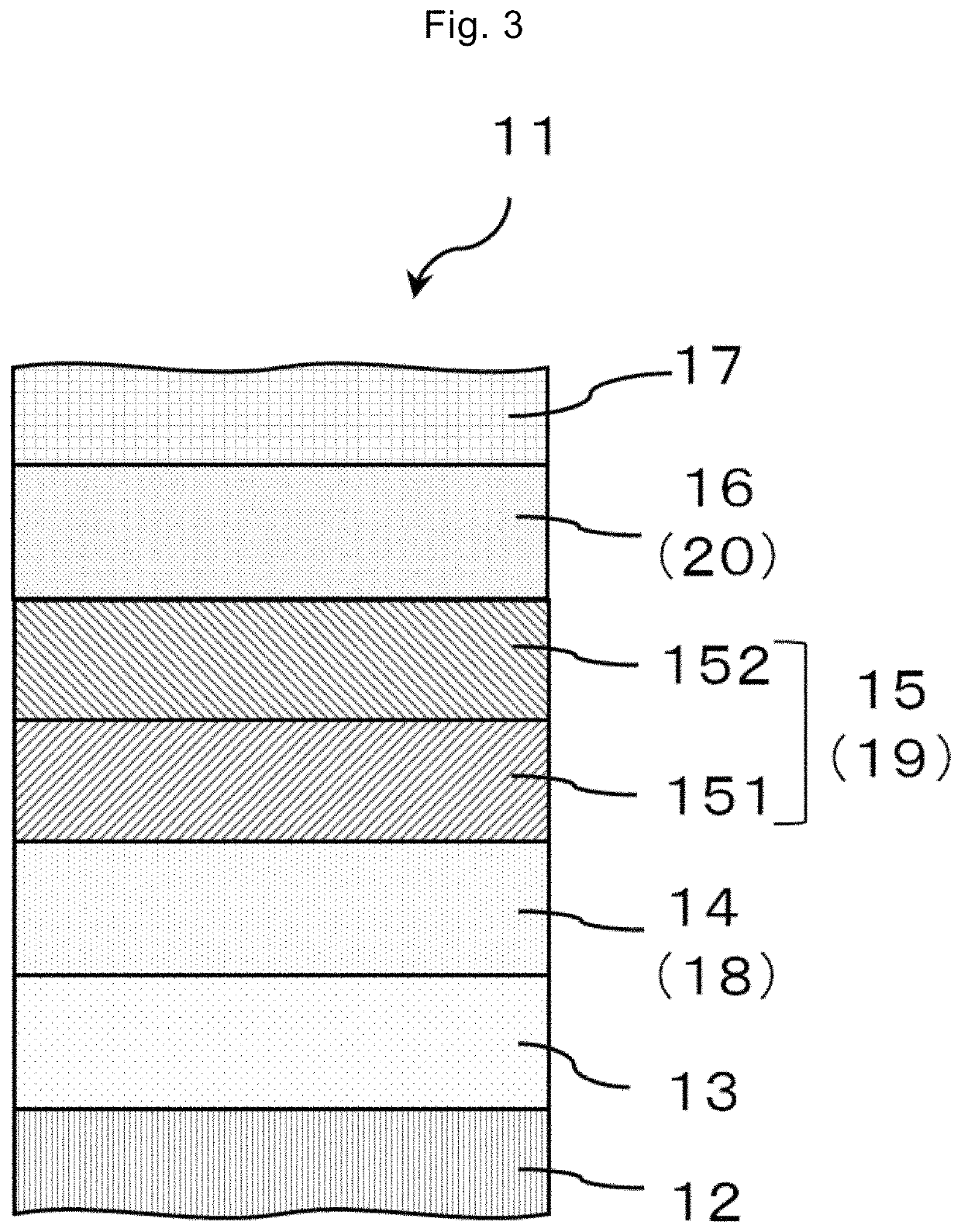
[0096]Next, an example of the perpendicular MTJ film and perpendicular MTJ element according to an embodiment of the present invention will be described with reference to FIG. 14 and FIG. 15. As the MTJ film, a multilayer film having a structure of MgO (001) single crystal substrate / Cr (40 nm) / iron-based alloy layer Fe—Al (1 nm) / Mg (0.2 nm) / Mg—Al (tMgAl)-indirect plasma oxidation / Fe (0.1 nm) / Co—Fe—B (1.4 nm) / Ta (2 nm) / Ru (8 nm) was formed by sputter deposition and plasma oxidation. Here, tMgAl is the Mg—Al film thickness. The Fe—Al composition was Fe72Al28, and the Mg—Al composition was Mg40Al60. In addition, the Mg / Mg—Al layer is converted to a Mg—Al—O layer by indirect plasma oxidation. In this perpendicular MTJ film, the same method as that for the perpendicularly magnetized film structure of Example 1 was used as the manufacturing method from the MgO substrate to the Mg—Al—O layer.

[0097]The Mg—Al—O layer was post-annealed in a vacuum chamber at 250° C. for 15 minutes to improve ...


PUM

PropertyMeasurementUnit
temperatureaaaaaaaaaa
thicknessaaaaaaaaaa
thicknessaaaaaaaaaa

Abstract

The present invention provides a perpendicularly magnetized film structure exhibiting high interface-induced magnetic anisotropy by utilizing a combination of an alloy comprising Fe as a main component and MgAl2O4 as a basic configuration.

Description

TECHNICAL FIELD[0001]The present invention relates to a precursor structure of a perpendicularly magnetized film including a stacked film of a ferromagnetic thin film and an oxide thin film, and a perpendicularly magnetized film structure and a method for manufacturing the same. The present invention also relates to a perpendicular magnetization-type magnetic tunnel junction film in which the perpendicularly magnetized film structure is used and a method for manufacturing the same. The present invention further relates to a perpendicular magnetization-type magnetic tunnel junction element in which the perpendicularly magnetized film structure or magnetic tunnel junction film is used.BACKGROUND ART[0002]Along with the advances in high density recording and capacity increase with respect to magnetic disk devices (hard disks) and magnetoresistive random access magnetic memory (MRAM) that use ferromagnetic thin film structures, perpendicularly magnetized films that are magnetized in the...

Claims


Application Information

Patent Timeline
Patent Type & Authority Patents(United States)
IPC IPC(8): H01L43/10G01R33/09H01L43/12H01L27/22H01F10/14H01L43/08H10N50/01H10N50/10
CPCH01L43/10G01R33/09H01F10/14H01L27/222H01L43/08H01L43/12H01F10/30G01R33/098G01R33/0052H01F10/3254H01F10/3286H01F41/303G11C11/161H10N50/01H10N50/85H10N50/10H10B61/00
Inventor SUKEGAWA, HIROAKISCHEIKE, THOMASMITANI, SEIJI
Owner NAT INST FOR MATERIALS SCI
Learn More