
Desmearing method and desmearing device

a desmearing device and desmearing method technology, which is applied in the manufacture of printed circuits, printed circuit parts, printed circuits, etc., can solve the problems of long time required, large cost of wet-type desmearing process, and insufficient penetration of alkaline solution into via holes, etc., and achieve greater oxidizability

Active Publication Date: 2021-08-24
USHIO DENKI KK
View PDF11 Cites 0 Cited by
  • Summary
  • Abstract
  • Description
  • Claims
  • Application Information

AI Technical Summary

Benefits of technology

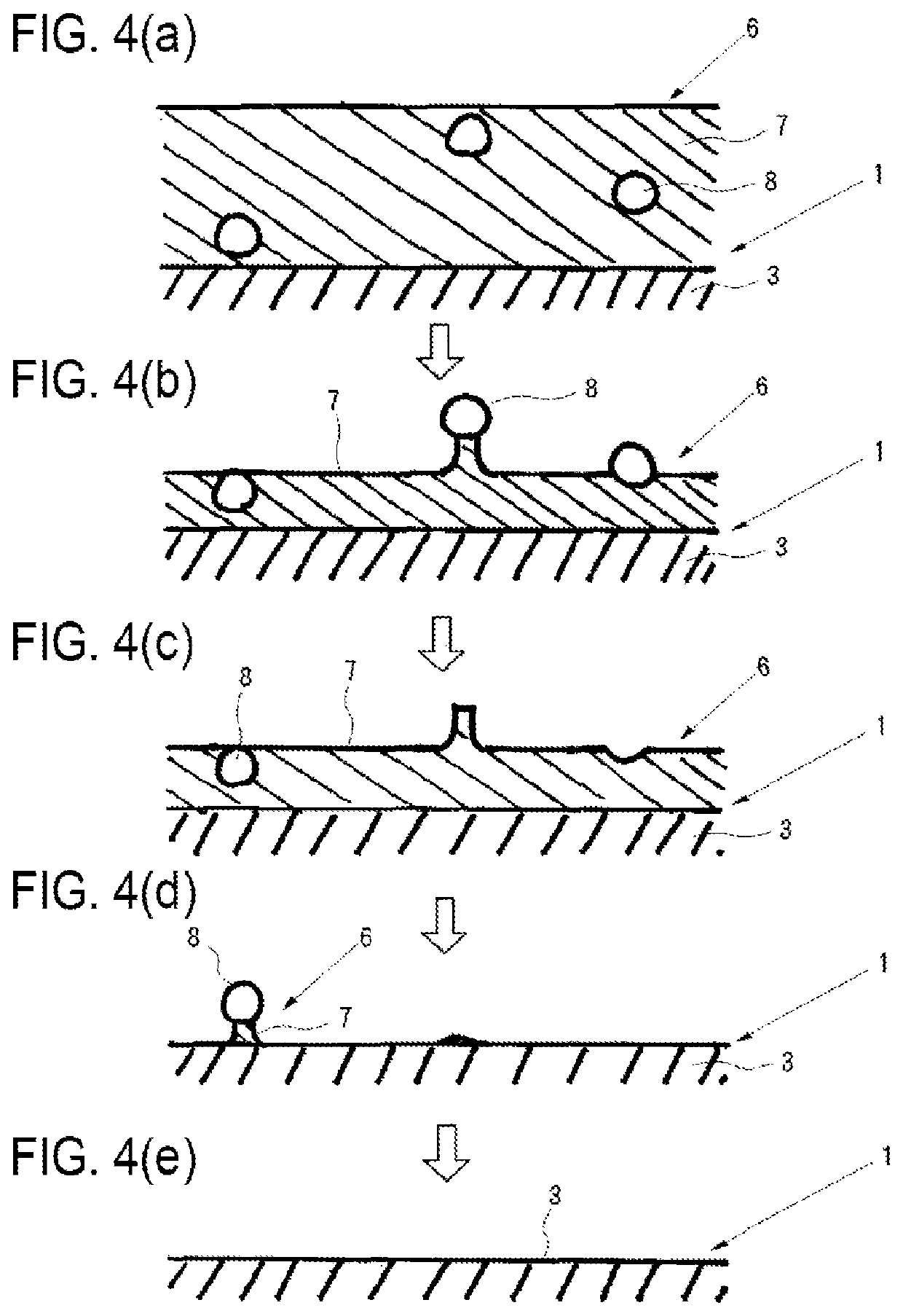
The present invention provides a desmearing method that can effectively remove smears derived from both organic and inorganic substances from wiring substrate materials using ultraviolet irradiation and physical vibration treatment. The method eliminates the need for chemicals that would require waste liquid treatment and reduces the time required for the desmearing process.

Problems solved by technology

However, the wet-type desmearing process has problems, e.g., a long time is required to dissolve the smear in the alkaline solution, a cleaning process and a neutralizing process are necessary after the wiring substrate material is immersed in the alkaline solution, and a waste liquid treatment is needed to the alkaline solution after it is used in the process.
Thus, the wet-type desmearing process becomes considerably costly.
When the desmearing process is carried out to the wiring substrate material having small-diameter via holes, the alkaline solution does not penetrate into the via holes sufficiently.
Thus, it is difficult to reliably perform a desmearing process in a desired manner.
Also, the cleaning and neutralization to the wiring substrate material is unnecessary, and the waste liquid treatment is unnecessary.
However, the inventors found that the conventional dry-type desmearing process had the following problems.

Method used


Image

  • Desmearing method and desmearing device
  • Desmearing method and desmearing device
  • Desmearing method and desmearing device

Examples


example 1

[0183]The ultraviolet irradiation treatment and the physical vibration treatment, which will be described below, were applied to the sample wiring substrate material to carry out the desmearing treatment to the sample wiring substrate material.

(1) Ultraviolet Irradiation Treatment Step

[0184]In the atmosphere, the interior of the through hole of the sample wiring substrate material was irradiated with an ultraviolet beam, which was emitted from an ultraviolet irradiation device having a xenon excimer lamp, under the following conditions.

Conditions for Ultraviolet Irradiation Treatment:

[0185]Ultraviolet irradiance at an outer surface of an ultraviolet emission window of the ultraviolet irradiation device was 40 W / cm2.

[0186]Distance between the ultraviolet emission window of the ultraviolet irradiation device and the sample wiring substrate material was 3 mm.

[0187]Ultraviolet irradiation time was 180 minutes.

(2) Physical Vibration Treatment Step

[0188]After the ultraviolet irradiation t...

example 2

[0193]The ultraviolet irradiation treatment and the physical vibration treatment, which will be described below, were alternately applied three times to the sample wiring substrate material to carry out the desmearing process to the sample wiring substrate material. After the desmearing process, the same evaluation as Example 1 was conducted to the sample wiring substrate material. Results of the evaluation are shown in Table 1.

(1) Ultraviolet Irradiation Treatment Step

[0194]In the atmosphere, the interior of the through hole of the sample wiring substrate material was irradiated with an ultraviolet beam, which was emitted from an ultraviolet irradiation device having a xenon excimer lamp, under the following conditions. After the desmearing process, the same evaluation as Example 1 was conducted to the sample wiring substrate material. Results of the evaluation are shown in Table 1.

Conditions for Ultraviolet Irradiation Treatment:

[0195]Ultraviolet irradiance at an outer surface of ...

example 3

[0199]The ultraviolet irradiation treatment and the physical vibration treatment, which will be described below, were applied to the sample wiring substrate material to carry out the desmearing process to the sample wiring substrate material. After the desmearing process, the same evaluation as Example 1 was conducted to the sample wiring substrate material. Results of the evaluation are shown in Table 1.

(1) Ultraviolet Irradiation Treatment Step

[0200]The interior of the through hole of the sample wiring substrate material was irradiated with the ultraviolet beam in the same manner as Example 1.

(2) Physical Vibration Treatment Step

[0201]After the ultraviolet irradiation treatment, which is described above in the (1) section, the compressed air of 0.2 MPa was injected to the interior of the through hole of the sample wiring substrate material for ten seconds while the compressed air is being caused to vibrate with a supersonic wave of 30.0 kHz.


PUM

PropertyMeasurementUnit
wavelengthaaaaaaaaaa
grain diameteraaaaaaaaaa

Abstract

Provided are a desmearing method and a desmearing device which are able to reliably remove a smear derived from any of an inorganic substance and an organic substance, and eliminate the need to use a chemical that requires a waste liquid treatment. The desmearing method of the present invention is directed to a desmearing method for a wiring substrate material that is a laminated body of insulating layers made from resin containing a filler and a conductive layer, and includes an ultraviolet irradiation treatment step for irradiating the wiring substrate material with ultraviolet beams with a wavelength of 220 nm or less, and a physical vibration treatment step for applying physical vibrations to the wiring substrate material which has undergone the ultraviolet irradiation treatment step.

Description

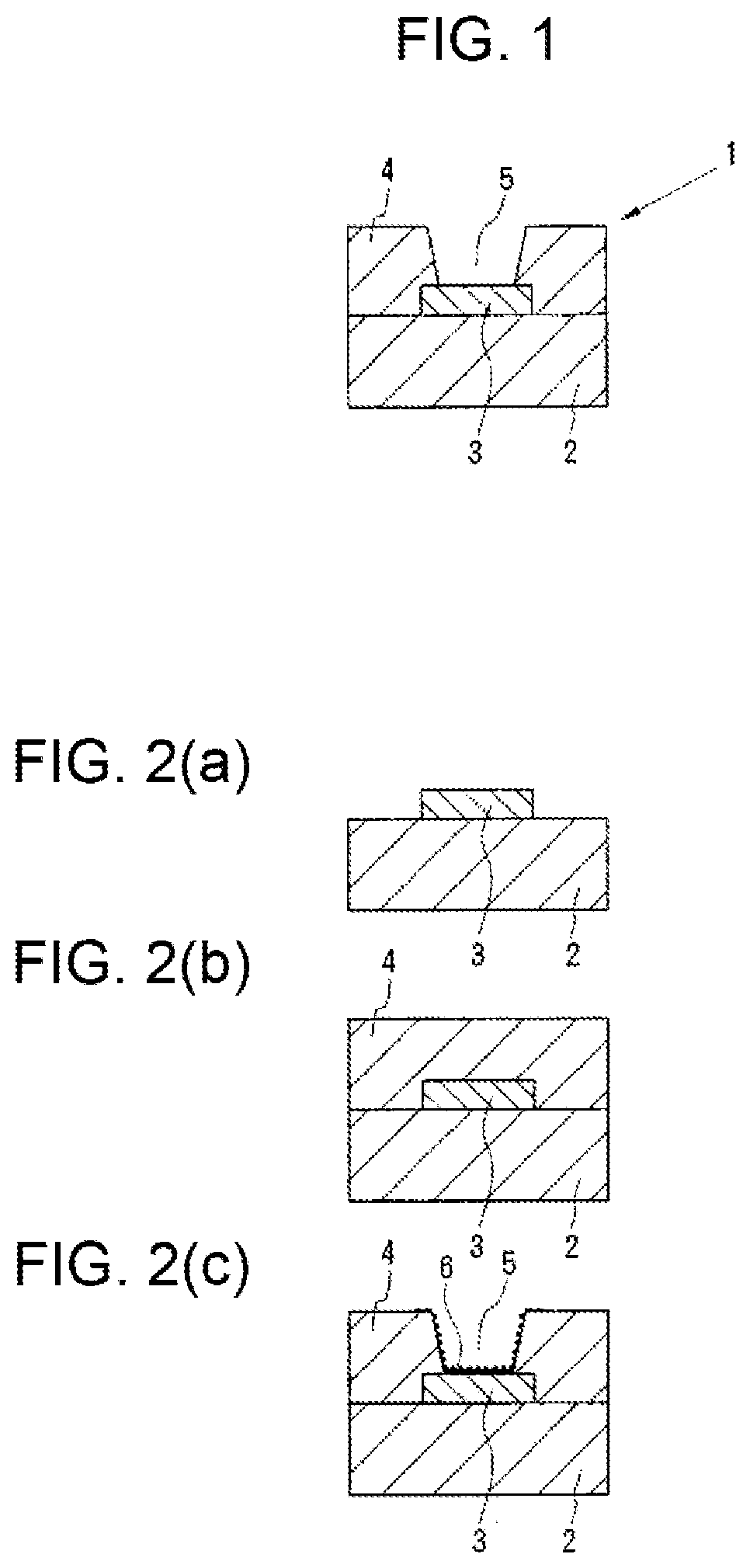
TECHNICAL FIELD[0001]The present invention relates to a desmearing method and a desmearing device, which are applied to a wiring substrate material including a laminated body of insulation layers, which are made from resin containing a filler, and a conductive layer.BACKGROUND ART[0002]For example, one of known wiring substrates that support semiconductor elements, such as semiconductor integrated circuit elements, thereon is a multi-layer wiring substrate that includes insulation layers and conductive layers (wiring layers) laminated alternately. In such multi-layer wiring substrate, via holes and / or through holes that extend through one or a plurality of insulation layers in a thickness direction of the insulation layer(s) are formed to electrically connect one conductive layer to another conductive layer[0003]In a process of fabricating a multi-layer wiring substrate, drilling and / or laser beam machining is applied to the wiring substrate material, which includes the laminated bo...

Claims


Application Information

Patent Timeline
Patent Type & Authority Patents(United States)
IPC IPC(8): H05K3/26H05K3/00H05K3/22H05K1/03
CPCH05K3/0088H05K1/0373H05K3/227H05K3/26H05K2201/0209H05K2203/0285H05K2203/0292H05K2203/075H05K2203/0743H05K2203/0766H05K2203/081H05K2203/087H05K2203/1509H05K3/0055
Inventor HIROSE, KENICHIHORIBE, HIROKIHABU, TOMOYUKIENDO, SHINICHI
Owner USHIO DENKI KK
Learn More