
Magnetic stack, multilayer, tunnel junction, memory point and sensor comprising such a stack

a magnetic stack and multilayer technology, applied in the direction of magnet bodies, instruments, substrate/intermediate layers, etc., can solve the problems of insatiable thermal stability of magnetic stacks, limited sot-mram type memory production, and inability to obtain desired crystalline structur

Active Publication Date: 2021-04-13
COMMISSARIAT A LENERGIE ATOMIQUE ET AUX ENERGIES ALTERNATIVES +2
View PDF6 Cites 3 Cited by
  • Summary
  • Abstract
  • Description
  • Claims
  • Application Information

AI Technical Summary

Benefits of technology

The invention is a magnetic stack that has excellent thermal stability and higher perpendicular magnetic anisotropy than existing stacks. This is achieved by using a refractory metal material with strong chemical bonds as the insertion layer, which reduces interface defects and smooths the interfaces between layers, resulting in increased perpendicular magnetic anisotropy at the interface. The refractory material also makes the stack mechanically rigid, increasing its stability during potential annealings at high temperature. The insertion layer also reduces the magnetization of the stack, resulting in an effective increase in perpendicular magnetic anisotropy. Overall, the refractory material and high melting temperature make the magnetic stack more robust and stable up to high temperatures.

Problems solved by technology

In a tunnel junction of BS-pMTJ type, it is thus impossible to obtain the desired crystalline structure using a seed layer having a given symmetry.
These difficulties greatly limit the production of SOT-MRAM type memories having high perpendicular magnetic anisotropy and their use in spintronic devices.
However, these known magnetic stacks have a thermal stability that is not satisfactory.
Indeed, they may lose their perpendicular anisotropy at annealing temperatures of the order of 300° C., which are too low compared to those required for an integration using CMOS (Complementary Metal Oxide Semiconductor) technology, which requires annealings at 400° C.
Furthermore, the materials I disclosed in the document FR2976396 do not make it possible to have interfaces between the different layers of the FM / I / X stack that are sufficiently smooth and regular.
Furthermore, these materials do not make it possible to avoid interfacial defects, notably those created during the growth of the layers X, often composed of heavy metals such as Pt or Pd.

Method used


Image

  • Magnetic stack, multilayer, tunnel junction, memory point and sensor comprising such a stack
  • Magnetic stack, multilayer, tunnel junction, memory point and sensor comprising such a stack
  • Magnetic stack, multilayer, tunnel junction, memory point and sensor comprising such a stack

Examples


Embodiment Construction

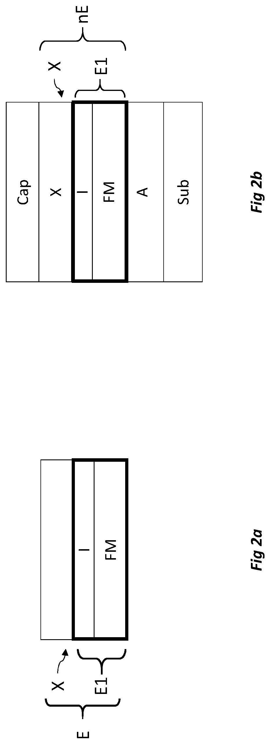
[0146]FIG. 2a shows an example of magnetic stack E according to the invention. The magnetic stack E according to the invention includes a first element E1 and a second element or second layer X, the second layer X being placed above the first element E1. The first element E1 may be a bilayer as is illustrated in FIG. 2a. In this case, the first element E1 includes a first layer FM and a second layer I of the first element. The first layer FM of the first element E1 is a ferromagnetic layer including at least one of the materials belonging to the first group of materials. The first group of materials includes the following materials: cobalt, iron, nickel and magnetic alloys based on these materials. The second element is here arranged directly on the first element.

[0147]The second layer I of the first element E1, also called insertion layer I, is a layer constituted of a refractory metal. The melting temperature of the second layer I of the first element E1 is above 1600° C. and pref...


PUM

PropertyMeasurementUnit
thicknessaaaaaaaaaa
thicknessaaaaaaaaaa
thicknessaaaaaaaaaa

Abstract

A magnetic stack includes a first element including a ferromagnetic layer; a second element including a metal layer able to confer on the assembly formed by the first and the second elements a magnetic anisotropy perpendicular to the plane of the layers. The first element further includes a refractory metal material, the second element being arranged on the first element.

Description

CROSS-REFERENCE TO RELATED APPLICATIONS[0001]This application claims priority to French Patent Application No. 1851302, filed Feb. 15, 2018, the entire content of which is incorporated herein by reference in its entirety.TECHNICAL FIELD OF THE INVENTION[0002]The present invention relates to a magnetic stack with out-of-plane magnetisation. “Magnetic stack with out-of-plane magnetisation” designates a magnetic stack that has a magnetisation substantially perpendicular to the plane along which extend the stack or plane of layers. One aim of the present invention is to propose a magnetic stack not needing to be deposited on a seed layer having a predetermined crystalline symmetry to obtain a strong magnetic anisotropy outside of the plane of the layers. This magnetic stack is advantageously able to withstand temperatures that are able to be high such as in particular those of post-deposition annealings (generally at a temperature above 300° C.) without degradation of the magnetic prope...

Claims


Application Information

Patent Timeline
Patent Type & Authority Patents(United States)
IPC IPC(8): G06F1/16H01L51/00G06F3/044G06F3/041H01L51/52H01L27/32H01F10/32H01L43/10H01L43/02H01L27/22G11C11/16G01R33/09H01F10/12H01F41/30H01L43/12H10N50/80H10N50/01
CPCH01F10/3286G01R33/098G11C11/161G11C11/1659G11C11/1675H01F10/12H01F10/3254H01L27/224H01L27/226H01L43/02H01L43/10H01F41/302H01L43/12H01F10/3272H10N50/85H10N50/10H10B61/10H10B61/20H10N50/80H10N50/01
Inventor CHATTERJEE, JYOTIRMOYVELOSO COELHO, PAULODIENY, BERNARDSOUSA, RICARDOPREJBEANU, LUCIAN
Owner COMMISSARIAT A LENERGIE ATOMIQUE ET AUX ENERGIES ALTERNATIVES
Learn More