
Method and apparatus for accumulating cross-aligned fiber in an electrospinning device

a technology of cross-aligning fiber and electrospinning device, which is applied in the field of electrospinning, can solve the problems of limiting the fabrication of larger-size mats, the method of destruction of a first fiber layer, and the non-uniform deposition of fiber branches on the target collector, so as to achieve optimal porosity and maximize surface contact

Active Publication Date: 2020-05-05
UNIVERSITY OF CENTRAL OKLAHOMA
View PDF10 Cites 14 Cited by
  • Summary
  • Abstract
  • Description
  • Claims
  • Application Information

AI Technical Summary

Benefits of technology

The present invention provides a method and apparatus to make cross-aligned nanofashioned membranes that can maximize surface contact with a wound and release biocides to prevent infection. The membranes also provide optimal porosity for cell migration and exudate flow, and can be used in wound care dressings for burns and injuries. The invention also simplifies the fabrication process and reduces manual steps, making it efficient and commercial viable.

Problems solved by technology

If not controlled, the branches of the fibers create a non-uniform deposition on the target collector.
A significant deficiency in the method was reported to be the destruction of a first fiber layer while forming a second cross-aligned fiber layer.
This appears to be a limiting factor in fabricating larger size mats because the fibers in the first layer cannot withstand the forces imparted by higher rotation speeds needed to apply the second layer.
Opposing disks, and both parallel wires and plates may be used to achieve fiber alignment and cross-alignment, but these known methods all suffer significant challenges in scalability for commercial applications, particularly as the physical dimensions of width and length of the desired mat are increased.
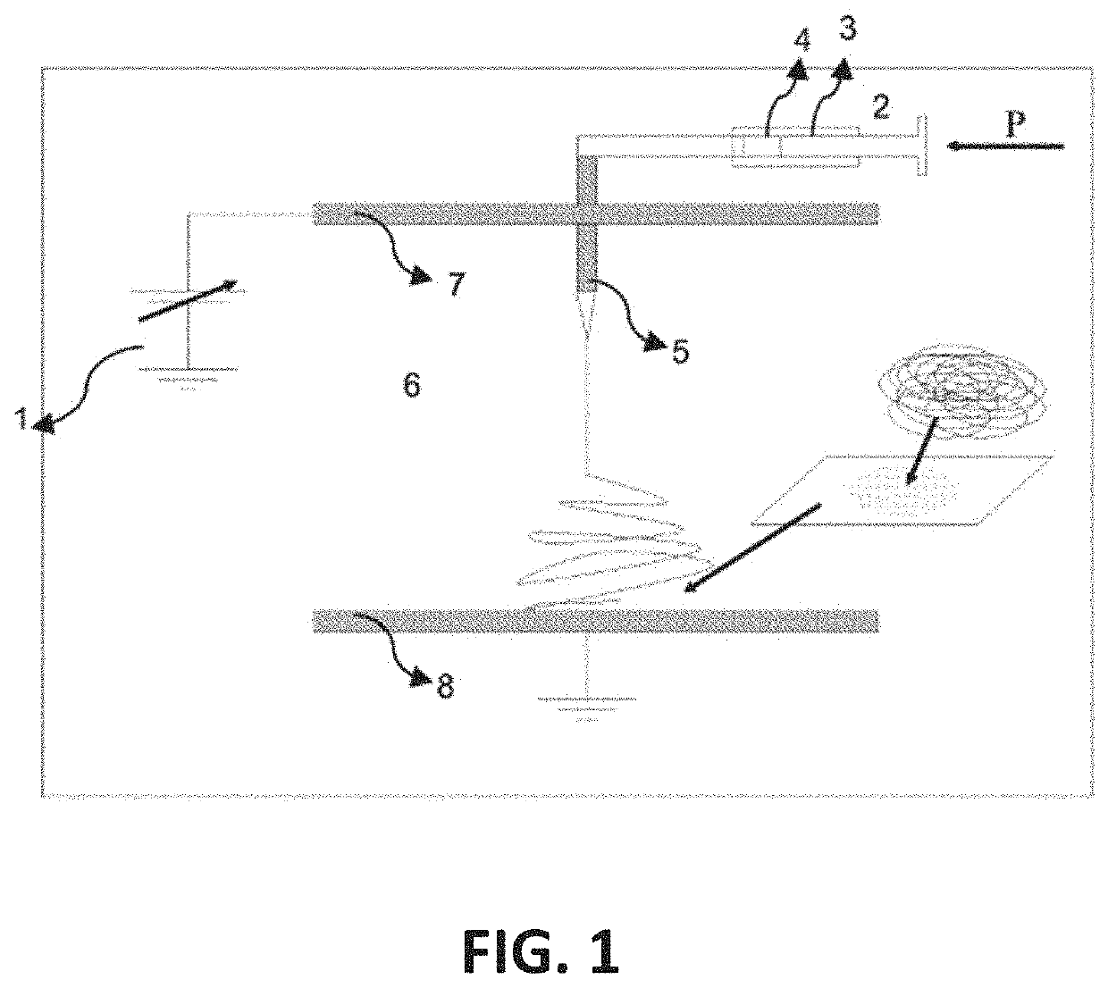
Growth of electrical bending instability (also known as whipping instability) and further elongation of the jet may be accompanied with the jet branching and / or splitting.
Such branching produces non-uniform deposition of fiber on a collector during the electrospin process.
Chronic wound care consumes a massive share of total healthcare spending globally.
In Canada, the estimated cost to the health system is $3.9 billion.
Despite significant progress over the past decade in dealing with chronic (non-healing) wounds, the problem remains a significant challenge for healthcare providers and continues to worsen each year given the demographics of an aging population.
Chronic wounds take a long time to heal and patients can suffer from chronic wounds for many years.
Wound dressings are often extremely painful to remove, particularly for severe burn wounds.
The removal of these dressings can peel away the fresh and fragile skin that is making contact with the dressing, causing extreme pain and prolonged recovery time.
There is also a greater risk for infection and the onset of sepsis, which is can be fatal.
While the drum supports attached fibers and prevents layer destruction during rotation unlike the method reported by Zhang, et al., repeated manual removal of the Kapton® film reportedly results in some misalignment of the collected fibers, which distorts the cross-alignment of fibers in the resulting fiber mat.
Further, the labor cost and production time associated with repeated manual removal of the Kapton® film and reattachment on the collector is cost prohibitive in commercial applications of electrospinning.
A method and apparatus to fabricate larger-size, well-structured membranes comprising cross-aligned electrospun fiber from many fiber branches, without fiber layer destruction and manual processes, has not been solved.

Method used


Image

  • Method and apparatus for accumulating cross-aligned fiber in an electrospinning device
  • Method and apparatus for accumulating cross-aligned fiber in an electrospinning device
  • Method and apparatus for accumulating cross-aligned fiber in an electrospinning device

Examples


examples

[0115]The present disclosure can be better understood with reference to the following non-limiting examples.

[0116]Nanofiber scaffolding structures and aligned fibers produced using the apparatus and methods of the present invention have applications in medicine, including artificial organ components, tissue engineering, implant material, drug delivery, wound dressing, and medical textile materials. Nanofiber scaffolding structures may be used to fight against the HIV-1 virus, and be able to be used as a contraceptive. In wound healing, nanofiber scaffolding structures assemble at the injury site and stay put, drawing the body's own growth factors to the injury site. These growth factors comprise naturally occurring substances such as proteins and steroid hormones capable of stimulating cellular growth, proliferation, healing, and cellular differentiation. Growth factors are important for regulating a variety of cellular processes. By controlling scaffold structure porosity, growth f...


PUM

PropertyMeasurementUnit
electrically chargeableaaaaaaaaaa
electricallyaaaaaaaaaa
conductiveaaaaaaaaaa

Abstract

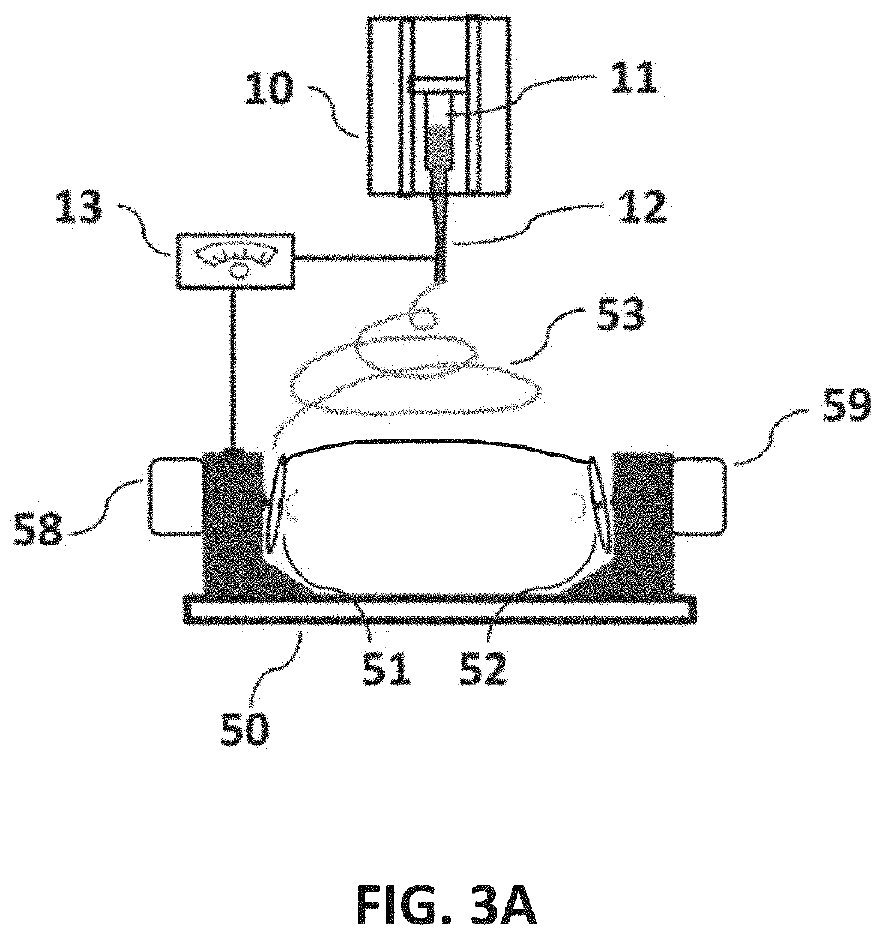
An apparatus for accumulating cross-aligned fiber in an electrospinning device, comprising a multiple segment collector including at least a first segment, a second segment, and an intermediate segment, the intermediate segment positioned between the first and second segment to collectively present an elongated cylindrical structure; at least one electrically chargeable edge conductor circumferentially resident on the first segment and circumferentially resident on the second segment; a connection point on the first segment and on the second segment, the connection points usable for mounting the elongated cylindrical structure on a drive unit to rotate around a longitudinal axis; the elongated cylindrical structure holding electrospun fiber substantially aligned with the longitudinal axis when the edge conductors are excited with a charge of opposite polarity relative to charged fiber, and attracting electrospun fiber on to its surface around the longitudinal axis at least when the edge conductors are absent a charge or grounded.

Description

STATEMENT AS TO RIGHTS TO INVENTIONS MADE UNDER FEDERALLY SPONSORED RESEARCH OR DEVELOPMENT[0001]This invention was made without government support.FIELD OF THE INVENTION[0002]The present invention generally relates to the field of electrospinning. More specifically, the invention relates to the controlled accumulation of cross-aligned fibers of micron to nano size diameters on a collector to produce layered structures in various dimensions from an electrospin process.[0003]All of the references, patents. and patent applications that are referred to herein are incorporated by reference in their entirety as if they had each been set forth herein in full. Note that this application is one in a series of applications by the Applicant covering methods and apparatus for enabling biomedical applications of nanofibers. The term “fiber” and the term “nanofiber” may be used interchangeably, and neither term is limiting. The disclosure herein goes beyond that needed to support the claims of t...

Claims


Application Information

Patent Timeline
Patent Type & Authority Patents(United States)
IPC IPC(8): D01D5/00D04H3/02B05B5/053B05C19/02B05B5/14B05B5/08B05D3/02
CPCB05B5/14B05C19/025B05D3/0254B05B5/0536B05B5/082D01D5/0092D04H3/02D01D5/0084D04H1/728D01D5/0076B05C19/002
Inventor HAFF, MAURICE
Owner UNIVERSITY OF CENTRAL OKLAHOMA
Learn More