Mechanical high spin-shock testing machines
a testing machine and spin-shock technology, applied in the field of spin-shock testing machines, can solve the problems of prohibitively high cost of engineering development of such components and their reliability testing, which requires testing of a large number of samples, and achieve the effect of short tim
- Summary
- Abstract
- Description
- Claims
- Application Information
AI Technical Summary
Benefits of technology
Problems solved by technology
Method used
Image
Examples
embodiment 10
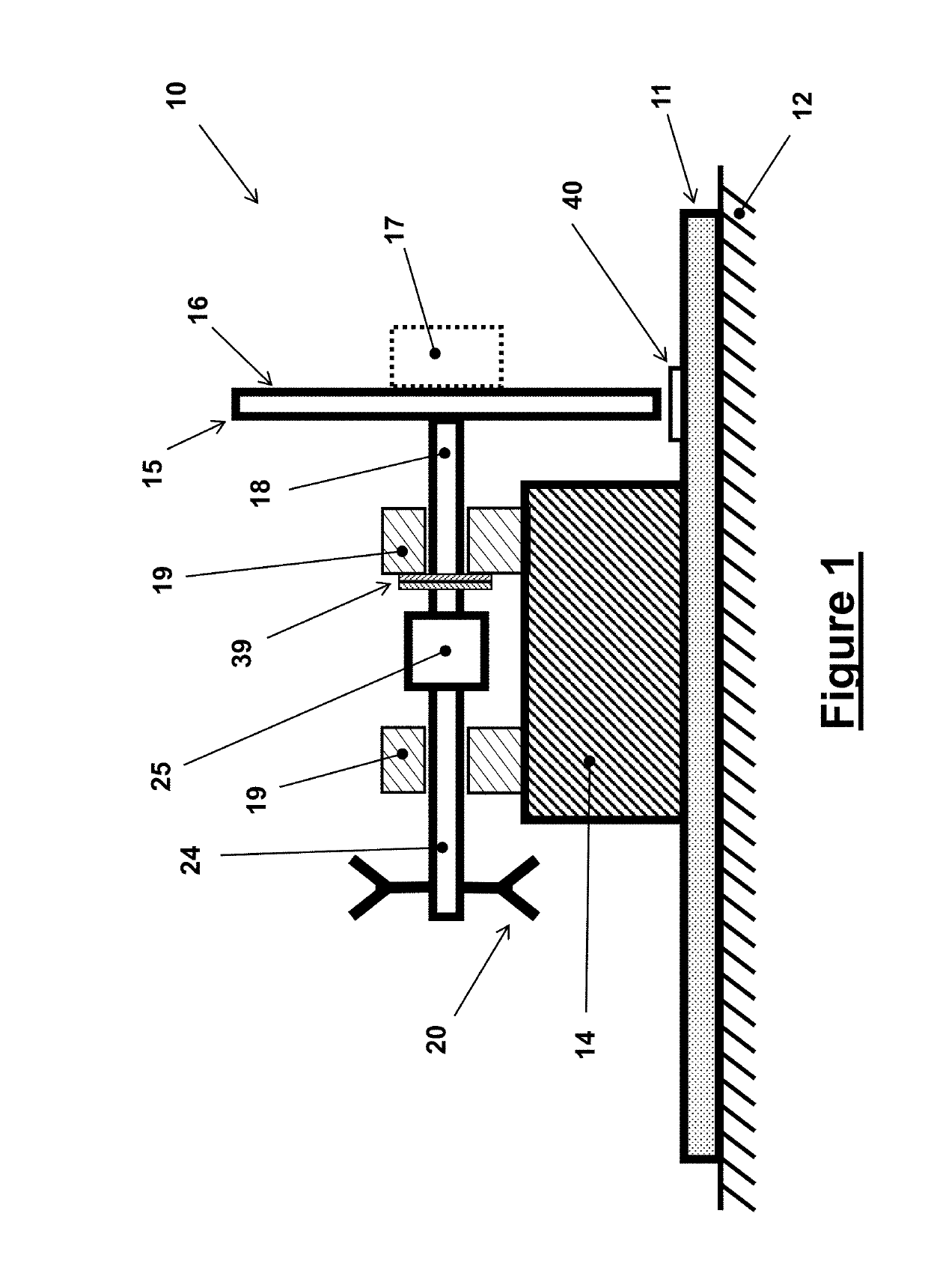
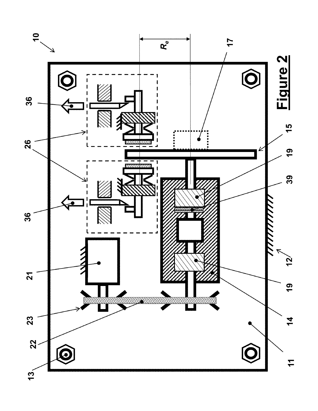
[0034]The basic design and operation of the mechanical rotary shock-testing machine is shown in the schematic of FIG. 1 and is indicated as the embodiment 10. The mechanical rotary shock testing machine 10 is constructed over a base plate 11, which can be made out of a heavy and thick steel plate which is firmly anchored to the machine foundation 12 by at least four heavy anchoring bolts (13 in FIG. 2) that are far enough apart around the base plate to resist the high torque reaction pulses (shocks) in reaction to the rotary shock loading pulses generated by the mechanical rotary shock testing machine 10. The top view of this embodiment 10 of the mechanical rotary shock testing machine is shown in FIG. 2. Certain relatively stiff shock absorbing elements (not shown) may be provided between the base 11 and the foundation 12 to prevent damage to the foundation structure. In heavier machinery, a relatively large (usually made out of reinforced concrete) foundation block (not shown) can...
embodiment 50
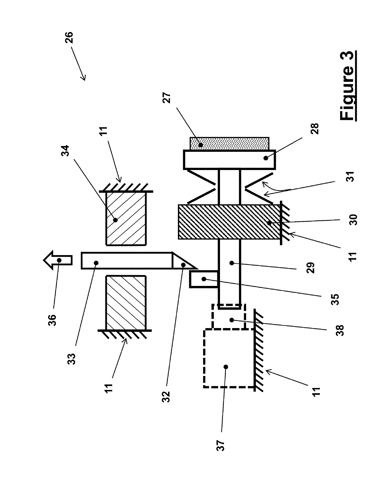
[0057]The braking units 26 shown in the schematic of FIG. 3 are designed to apply braking force to one or the other surface of the testing platform disc 15 or independently to both sides of the said disc as shown in FIG. 2. The braking units 26 similarly applies braking forces to one or independently to both sides of the disc brakes 43 of the mechanical rotary shock testing machine embodiment 50 shown in the schematic FIG. 5. It will be, however, appreciated by those skilled in the art that the best method of applying braking forces to a rotating disc is by applying equal but opposite forces to the sides of the disc and with the resultant force being as collinear as possible so that they would not subject the disc to a bending moment. As a result, the braking disc can be relatively thin, thereby reducing the overall system moment of inertia and the decelerating friction generated torque needed to apply a prescribed deceleration rate to the components being tested 17. In addition, th...
PUM
| Property | Measurement | Unit |
|---|---|---|
| braking force | aaaaa | aaaaa |
| velocity | aaaaa | aaaaa |
| acceleration | aaaaa | aaaaa |
Abstract
Description
Claims
Application Information
 - R&D
- Intellectual Property
- Life Sciences
- Materials
- Tech Scout
- Unparalleled Data Quality
- Higher Quality Content
- 60% Fewer Hallucinations
Browse by: Latest US Patents, China's latest patents, Technical Efficacy Thesaurus, Application Domain, Technology Topic, Popular Technical Reports.
© 2025 PatSnap. All rights reserved.Legal|Privacy policy|Modern Slavery Act Transparency Statement|Sitemap|About US| Contact US: help@patsnap.com


