Hybrid vehicle
a hybrid vehicle and hybrid technology, applied in the field of hybrid vehicles, can solve the problems of limited running distance, inability to power generation using the engine output, and inability to continue running, etc., and achieve the effect of increasing the running distan
- Summary
- Abstract
- Description
- Claims
- Application Information
AI Technical Summary
Benefits of technology
Problems solved by technology
Method used
Image
Examples
first embodiment
[0030](Configuration of Hybrid Vehicle)
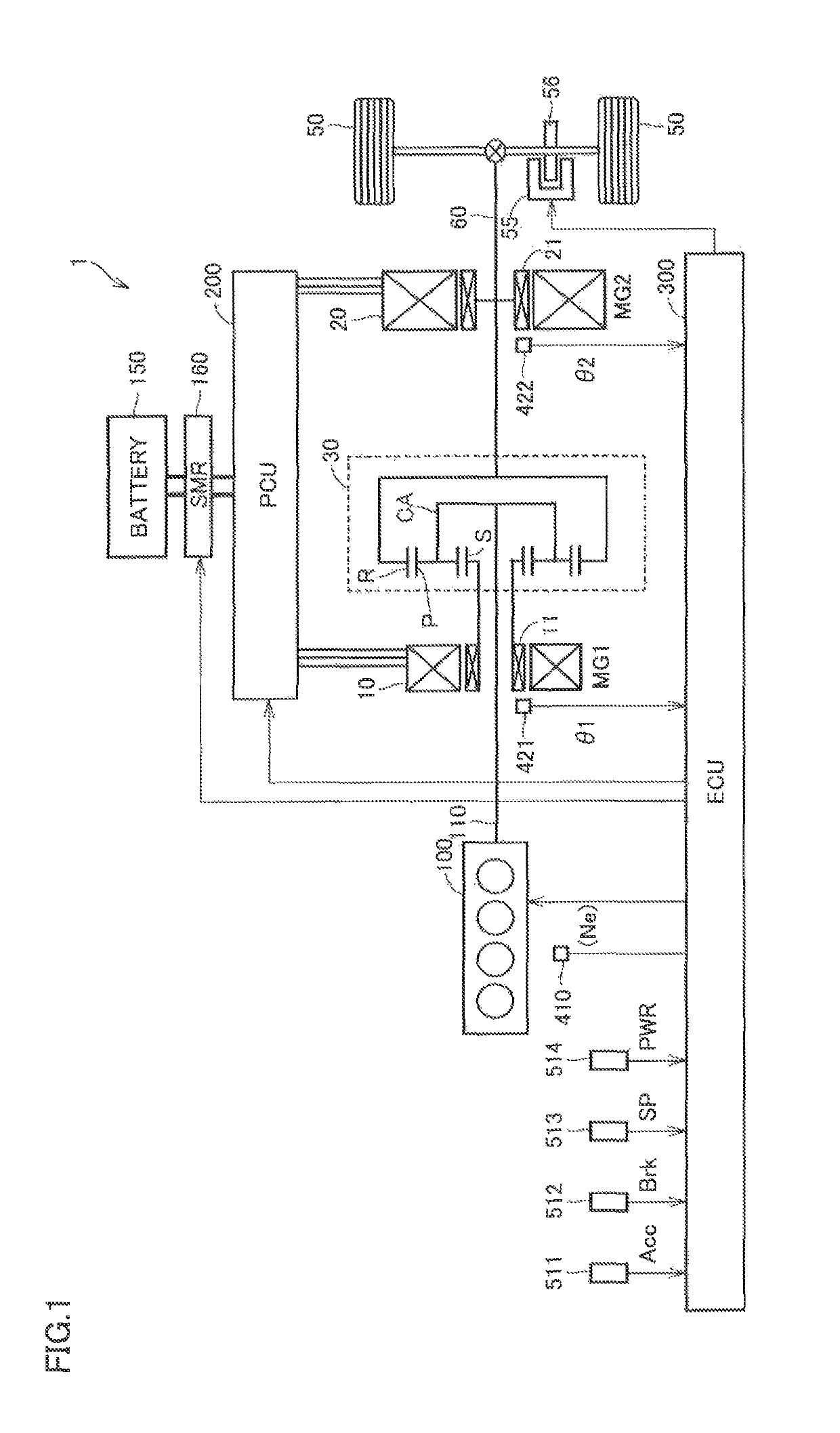
[0031]FIG. 1 is a block diagram schematically showing an overall configuration of a hybrid vehicle according to the present embodiment.
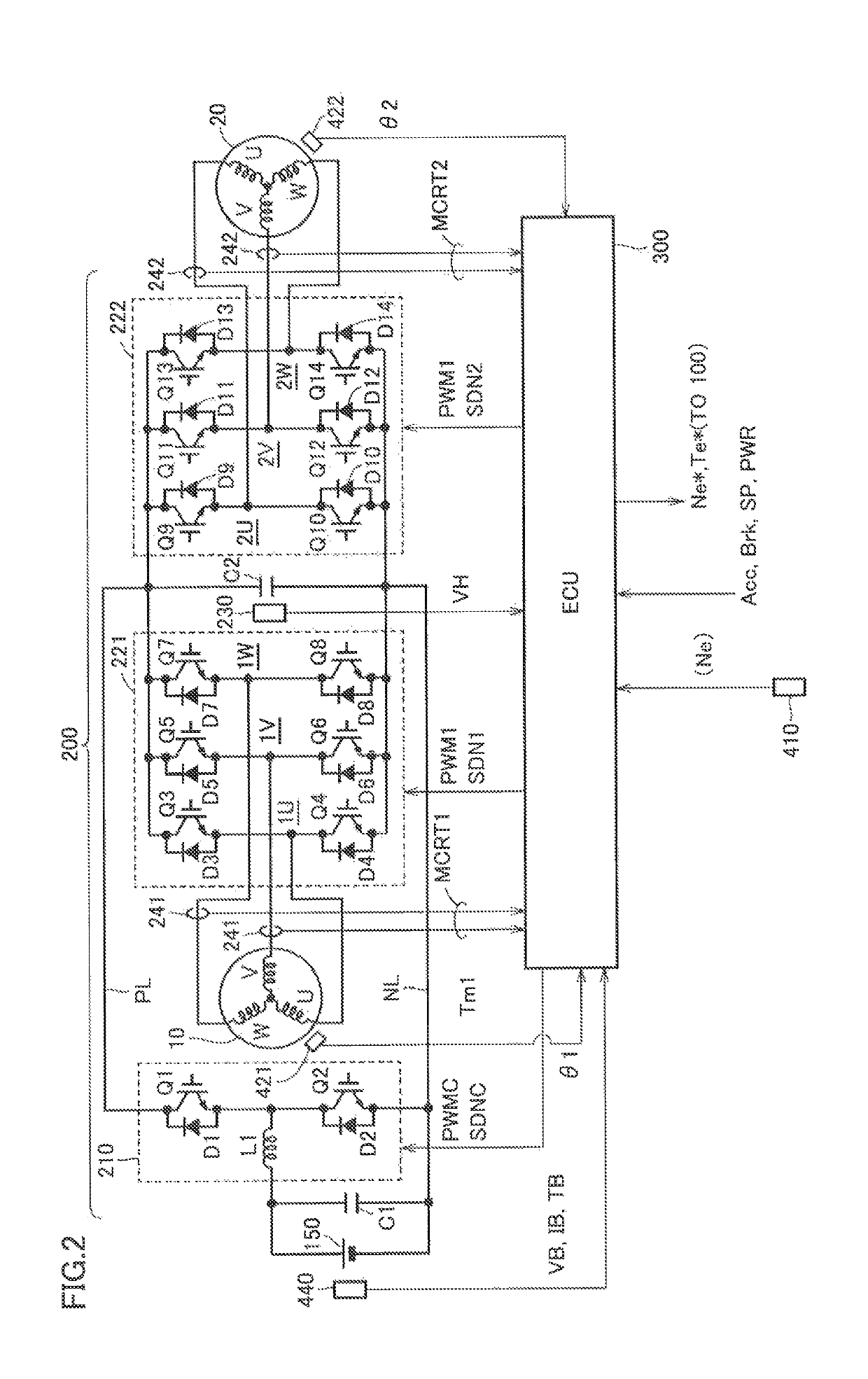
[0032]Referring to FIG. 1, a vehicle 1 includes an engine 100, motor generators 10 and 20, a planetary gear mechanism 30, drive wheels 50, an output shaft 60 connected to drive wheels 50, a battery 150 forming “power storage device”, a system main relay (SMR) 160, a power control unit (PCU) 200, and an electronic control unit (ECU) 300.
[0033]As described in detail later, vehicle 1 can switch the running mode of vehicle 1 between electric vehicle running (EV running) during which engine 100 is stopped and the motive power of only motor generator 20 is used, and hybrid vehicle running (HV running) during which engine 100 is actuated and the motive power of both engine 100 and motor generator 20 is used.
[0034]Engine 100 is an internal combustion engine that converts the thermal energy by fuel combustion into the me...
second embodiment
[0173]In a second embodiment, description will be given to the resolverless control when ECU 300 shown in FIG. 1 is arranged in a divided manner for each of a running control function, a motor generator control function and an engine control function. Similarly to the first embodiment, in the second embodiment as well, description will be given to control when an abnormality occurs in resolver 422 of motor generator 20 whereas resolver 421 of motor generator 10 can normally detect electric angle θ.
[0174]FIG. 12 is a functional block diagram for describing a distributed arrangement configuration of ECUs in a hybrid vehicle according to the second embodiment.
[0175]Referring to FIG. 12, in the hybrid vehicle according to the second embodiment, ECU 300 is divided into an HV-ECU 310 for executing integrated control and running control over vehicle 1, an MG-ECU 320 for controlling motor generators 10 and 20, and an engine ECU 330 for controlling engine 100. Furthermore, MG-ECU 320 has an ...
third embodiment
[0194]In the first and second embodiments, description has been given to the resolverless control and running of the vehicle when an abnormality occurs in the resolver of motor generator 20, of motor generators 10 and 20. However, the resolverless control described in the first embodiment can also be similarly applied to the case in which an abnormality occurs in the resolver of motor generator 10 (MG1). Therefore, in a third embodiment, description will be given to the resolverless control and running of the vehicle when an abnormality occurs in the resolver of motor generator 10.
[0195]Namely, in the third embodiment, the output of motor generator 20 is controlled in accordance with the control configuration shown in FIG. 6, while the resolverless control shown in FIG. 7 is applied to motor generator 10 to control the output torque of motor generator 10.
[0196]FIG. 13 shows a flowchart for describing a control process by the electric angle estimation unit (FIG. 7) in the resolverles...
PUM
 Abstract
Description
Claims
Application Information
 - R&D
- Intellectual Property
- Life Sciences
- Materials
- Tech Scout
- Unparalleled Data Quality
- Higher Quality Content
- 60% Fewer Hallucinations
Browse by: Latest US Patents, China's latest patents, Technical Efficacy Thesaurus, Application Domain, Technology Topic, Popular Technical Reports.
© 2025 PatSnap. All rights reserved.Legal|Privacy policy|Modern Slavery Act Transparency Statement|Sitemap|About US| Contact US: help@patsnap.com


