
Control apparatus for vehicular drive system

a control apparatus and vehicular drive technology, applied in fluid gearings, transportation and packaging, gearing, etc., can solve the problems of insufficient heat generation, risk of insufficient heat generation of vehicles, so as to reduce the deterioration of fuel economy of vehicles, increase the running distance of vehicles, and improve fuel economy

Active Publication Date: 2017-08-15
TOYOTA JIDOSHA KK
View PDF19 Cites 1 Cited by
  • Summary
  • Abstract
  • Description
  • Claims
  • Application Information

AI Technical Summary

Benefits of technology

The present invention relates to a system for controlling the operation of a fluid-operated power transmitting device in a vehicle. The invention aims to improve fuel economy by heating the working oil of the device while it is stalled, and to reduce the deterioration of fuel economy by promoting the warm-up of the automatic transmission. The invention also includes a heat exchanging device that can be used to warm up the engine and the automatic transmission during stall control of the fluid-operated power transmitting device. The stall control of the fluid-operated power transmitting device can be implemented when the heat exchanging device is in its heat-exchanging state, and the invention takes into account the fuel economy improvement effect of the heat exchanging device to determine when to implement the stall control. Overall, the invention aims to optimize the operation of the fluid-operated power transmitting device to improve fuel economy in vehicles.

Problems solved by technology

In a cold state of the vehicle in the stationary state, therefore, the vehicular drive system does not substantially generate a heat, and is not warmed up enough.
Although the engine may be operated in an idling state for its warm-up operation while the vehicle in the cold state is in the stationary state, this idling operation warms up only the engine, but does not warm up a transmission provided in the vehicular drive system.
In the vehicular drive system provided with the transmission, therefore, rotary members of the transmission in a cold state have a large degree of friction due to a relatively high degree of viscosity of a cold working oil used for the transmission because of not being warmed up of the transmission, for example, giving rise to a risk of deterioration of the fuel economy of the vehicle.

Method used


Image

  • Control apparatus for vehicular drive system
  • Control apparatus for vehicular drive system
  • Control apparatus for vehicular drive system

Examples


embodiment

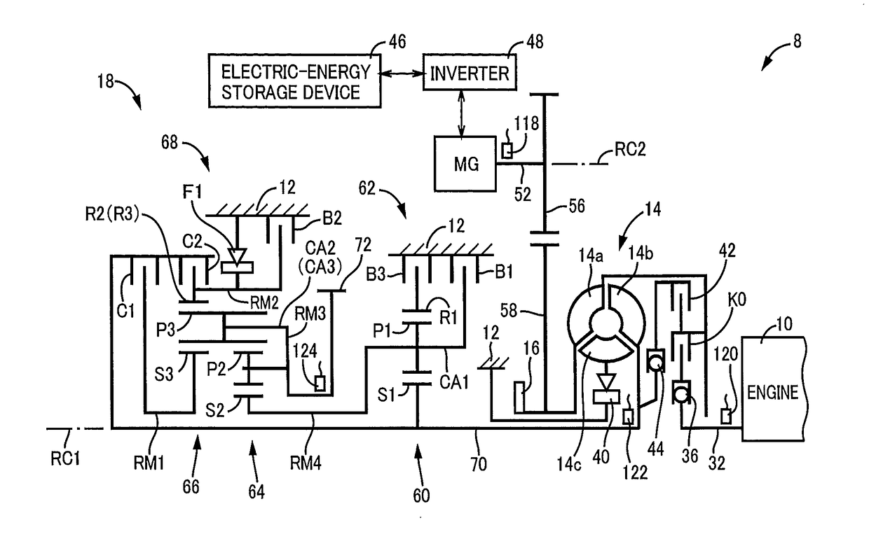
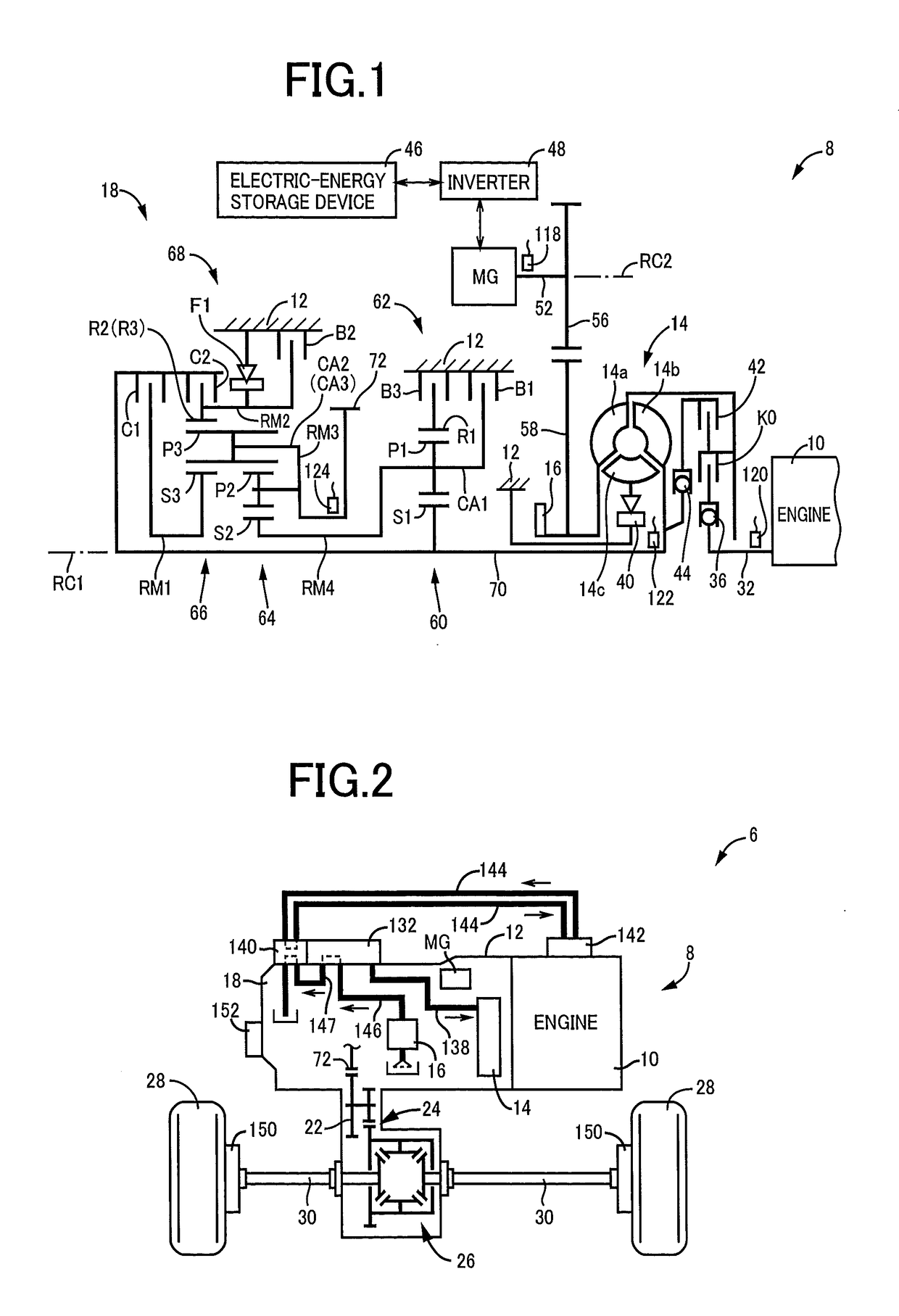
[0032]FIG. 1 is the schematic view of a vehicular drive system 8 (hereinafter referred to as “drive system 8”) to which the present invention is suitably applicable, and FIG. 2 is the view showing a power transmitting path from the drive system 8 to drive wheels 28. It is noted that an automatic transmission 18, a torque converter 14, etc. are substantially symmetric in construction with respect to their axes (first axis RC1), so that their lower halves are not shown in FIG. 1. The first axis RC1 shown in FIG. 1 represents the axes of an engine 10 and the torque converter 14, while a second axis RC2 represents the axis of an electric motor MG.

[0033]As shown in FIG. 1, the drive system 8 has the engine 10 of an water-cooled type such as a gasoline engine, a diesel engine or any other internal combustion engine, and a transaxle casing (T / A casing) 12 (hereinafter referred to as “casing 12”) which is a stationary member fixed to a vehicle body by bolts or any other fixing means. Within...


PUM


Abstract

A control apparatus for a vehicular drive system provided with an automatic transmission constituting a part of a power transmitting path between an electric motor and drive wheels, and a fluid-operated power transmitting device provided between the electric motor and the automatic transmission and having an input rotary element connected to said electric motor, and an output rotary element connected to said automatic transmission, includes a warm-up control implementing portion configured to implement a stall control of said fluid-operated power transmitting device wherein the input rotary element of said fluid-operated power transmitting device is rotated by said electric motor while the fluid-operated power transmitting device is placed in a stalling state.

Description

[0001]This is a 371 national phase application of PCT / JP2010 / 068767 filed 22[0002]Oct. 2010, the contents of which are incorporated herein by reference.TECHNICAL FIELD[0003]The present invention relates to a control operation to warm-up a vehicular drive system in a cold state, which is provided with an electric motor and a fluid-operated power transmitting device.BACKGROUND ART[0004]There is well known a control apparatus for a vehicular drive system provided with a vehicle driving electric motor, and a fluid-operated power transmitting device interposed between the electric motor and drive wheels of a vehicle. Patent Document 1 discloses an example of such a control apparatus for a vehicular drive system. This control apparatus is configured to reduce an amount of supply of an electric energy to the above-indicated electric motor for a predetermined length of time, if the electric motor has been kept operated for more than a predetermined period of time in an operating state of th...

Claims


Application Information

Patent Timeline
Patent Type & Authority Patents(United States)
IPC IPC(8): B60W30/18F16H39/00B60K6/48B60K6/547B60W10/02B60W10/08B60W10/115B60W20/00B60L50/16
CPCF16H39/00B60K6/48B60K6/547B60W10/023B60W10/08B60W10/115B60W20/00B60W30/18054B60W2710/1072B60Y2300/30B60Y2300/45Y02T10/6221Y10T477/631Y02T10/62B60W2510/1015
Inventor NATSUME, HIROSHI
Owner TOYOTA JIDOSHA KK
Learn More