
Tester with acceleration on memory and acceleration for automatic pattern generation within a FPGA block

a tester and acceleration technology, applied in automated test systems, error detection/correction, instruments, etc., can solve the problems of only testing duts, system cannot test duts, critical time consumed replacing hardware bus adapter cards, etc., to achieve the effect of keeping the bandwidth requirements of the system bus

Active Publication Date: 2018-12-25
ADVANTEST CORP
View PDF104 Cites 26 Cited by
  • Summary
  • Abstract
  • Description
  • Claims
  • Application Information

AI Technical Summary

Benefits of technology

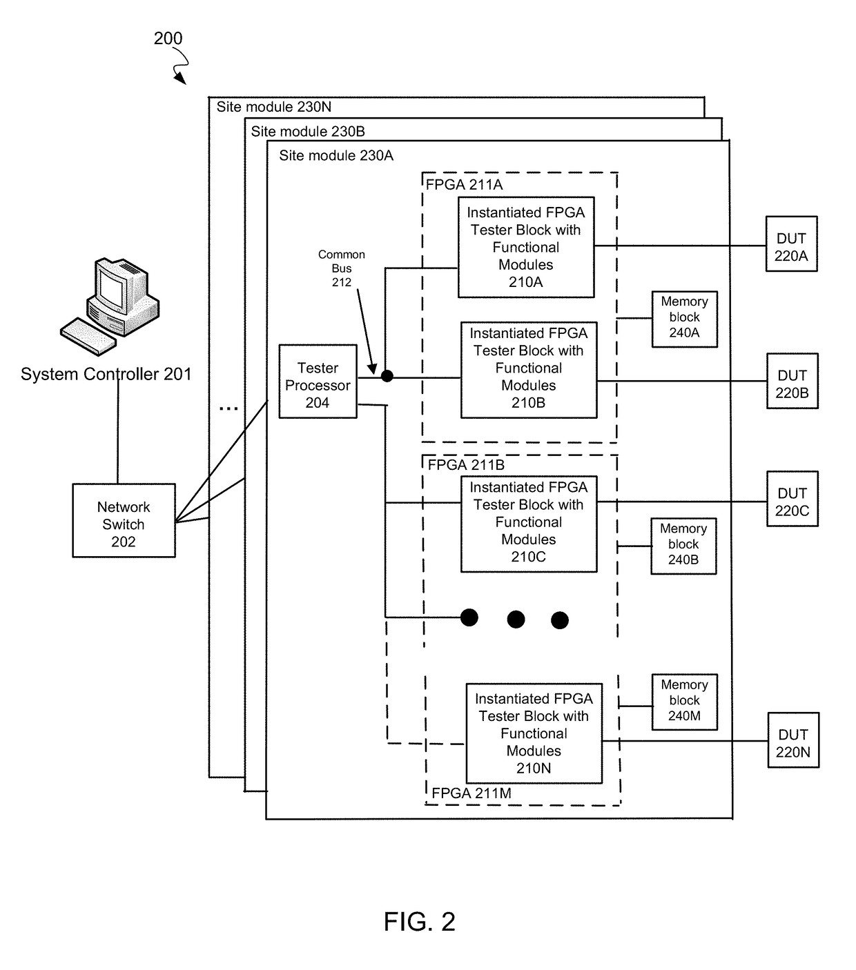
The patent text talks about a need for a tester architecture that can transfer the command and test pattern generation functionality onto the FPGA, reducing processing load and bandwidth requirements. It also suggests the need for a test architecture that allows more DUTs to be tested simultaneously than in prior configurations. Additionally, it proposes the use of programmable logic blocks on FPGA devices to eliminate the need for single purpose hardware bus adapter cards and facilitate reconfiguration of the communicative protocol engine.

Problems solved by technology

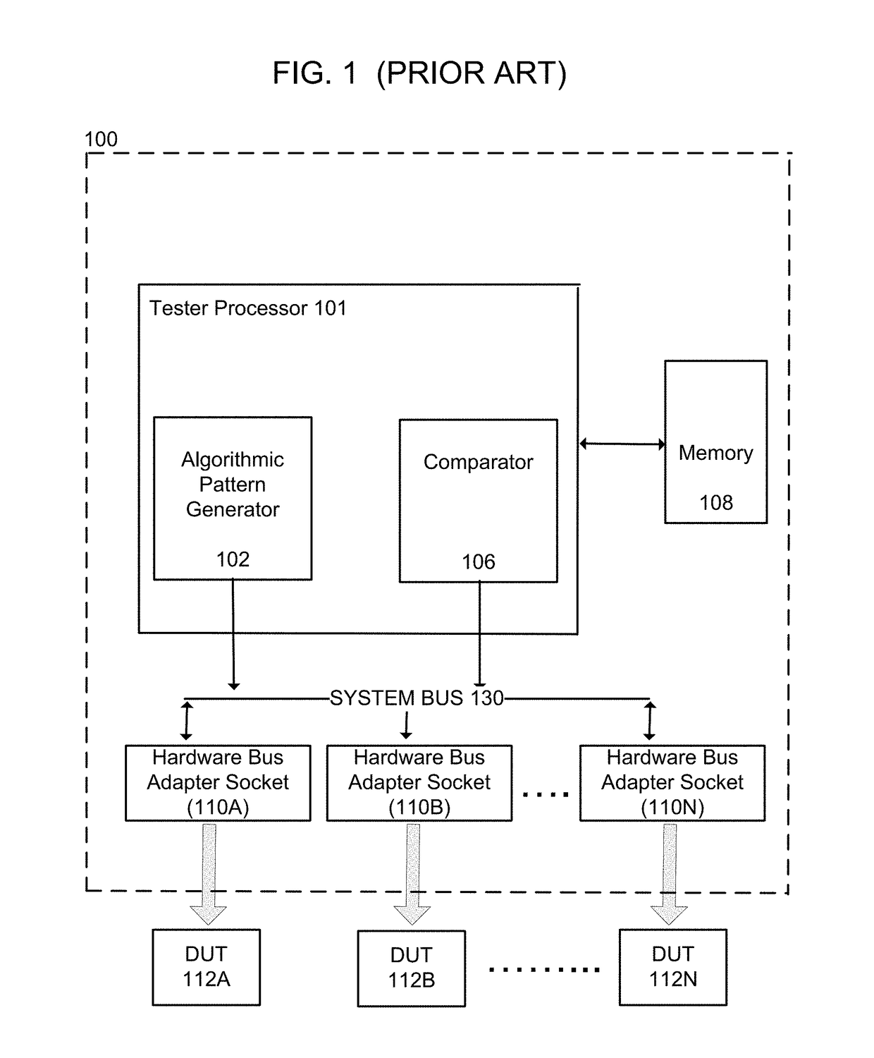
Because the tester processor is responsible for generating the commands and test patterns, the number of DUTs that can be tested with a given ATE body is limited by the processing capabilities of the tester processor.
Unless the PCIe hardware bus adapter cards are physically substituted with cards supporting the other protocol, such a system can only test DUTs that support the PCIe protocol.
Thus, on the test floor, critical time is consumed replacing hardware bus adapter cards when DUTs running a different protocol from the one that the existing adapter cards support need to be tested.

Method used


Image

  • Tester with acceleration on memory and acceleration for automatic pattern generation within a FPGA block
  • Tester with acceleration on memory and acceleration for automatic pattern generation within a FPGA block
  • Tester with acceleration on memory and acceleration for automatic pattern generation within a FPGA block

Examples


Embodiment Construction

[0037]Reference will now be made in detail to embodiments, examples of which are illustrated in the accompanying drawings. While the embodiments will be described in conjunction with the drawings, it will be understood that they are not intended to limit the embodiments. On the contrary, the embodiments are intended to cover alternatives, modifications and equivalents. Furthermore, in the following detailed description, numerous specific details are set forth in order to provide a thorough understanding. However, it will be recognized by one of ordinary skill in the art that the embodiments may be practiced without these specific details. In other instances, well-known methods, procedures, components, and circuits have not been described in detail as not to unnecessarily obscure aspects of the embodiments.

Notation and Nomenclature Section

[0038]Some regions of the detailed descriptions which follow are presented in terms of procedures, logic blocks, processing and other symbolic repr...


PUM


Abstract

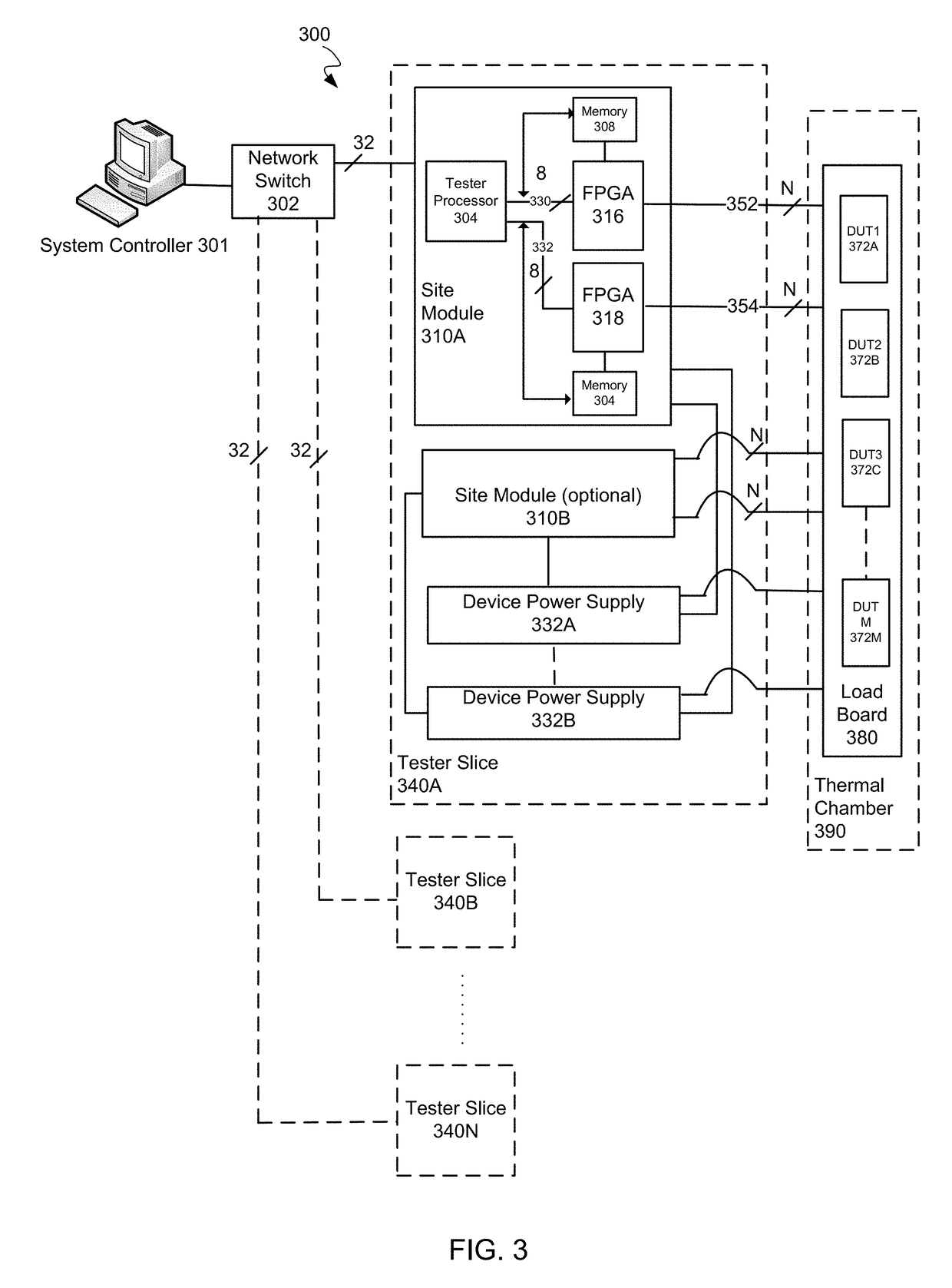
Automated test equipment capable of performing a high-speed test of semiconductor devices is presented. The automated test equipment apparatus comprises a computer system comprising a tester processor, wherein the tester processor is communicatively coupled to a plurality of FPGA components. Each of the plurality of FPGA components is coupled to a memory module and comprises: an upstream port operable to receive commands and data from the tester processor; a downstream port operable to communicate with a respective DUT from a plurality of DUTs; and a plurality of hardware accelerator circuits, wherein each of the accelerator circuits is configured to communicate with one of the plurality of DUTs. Each of the plurality of hardware accelerator circuits comprises a pattern generator circuit configurable to automatically generate test pattern data and a comparator circuit configured to compare data.

Description

CROSS-REFERENCE TO RELATED APPLICATIONSRelated Applications[0001]The present application is related to U.S. patent application Ser. No. 13 / 773,580, filed Feb. 21, 2013, entitled “TESTER WITH MIXED PROTOCOL ENGINE IN FPGA BLOCK,” naming John Frediani and Andrew Niemic as inventors. That application is incorporated herein by reference in its entirety and for all purposes.[0002]The present application is related to U.S. patent application Ser. No. 13 / 773,569, filed Feb. 21, 2013, entitled “A TEST ARCHITECTURE HAVING MULTIPLE FPGA BASED HARDWARE ACCELERATOR BLOCKS FOR TESTING MULTIPLE DUTS INDEPENDENTLY,” naming Gerald Chan, Andrew Niemic, Eric Kushnick, and Mei-Mei Sui as inventors. That application is incorporated herein by reference in its entirety and for all purposes.[0003]The present application is related to U.S. patent application Ser. No. 13 / 773,597, filed Feb. 21, 2013, entitled “GUI IMPLEMENTATIONS ON CENTRAL CONTROLLER COMPUTER SYSTEM FOR SUPPORTING PROTOCOL INDEPENDENT DEVI...

Claims


Application Information

Patent Timeline
Patent Type & Authority Patents(United States)
IPC IPC(8): G01R31/319G01R31/317G06F11/263G11C29/56G01R31/28
CPCG01R31/2834G01R31/31907G01R31/31724G11C29/56G01R31/31919G06F11/263G01R31/31903
Inventor FREDIANI, JOHNNIEMIC, ANDREW
Owner ADVANTEST CORP
Learn More