
Gas testing unit and method

a gas testing and gas technology, applied in the field of gas testing units and methods, can solve the problems of large capital expenditures needed for scale-up (e.g., process design and engineering), difficult to reproduce industrial c1-containing substrates at a remote facility, and difficult to achieve precise composition

Active Publication Date: 2018-10-30
LANZATECH NEW ZEALAND LTD
View PDF30 Cites 2 Cited by
  • Summary
  • Abstract
  • Description
  • Claims
  • Application Information

AI Technical Summary

Benefits of technology

The patent describes a way to identify and fix problems with a process that converts C1-containing substrates into other products. By testing the substrate and additives in a lab before using them in a larger process, the method improves accuracy and reduces costs. The demonstration also shows that the process works well with the actual substrate and additives that will be used in the real-world production process. Overall, this patent provides a way to ensure the biological conversion process works efficiently and reliably.

Problems solved by technology

Importantly, it has been determined that the precise composition of a given, industrial C1-containing substrate is often difficult to reproduce at a remote facility (e.g., a laboratory or a pilot-scale or demonstration-scale process), at least to the extent required for the accurate prediction of commercial performance.
Importantly, without sufficient confidence that a given process can achieve its performance objectives, large capital expenditures needed for scale-up (e.g., process design and engineering) cannot be justified.
In this regard, even trace amounts of certain contaminants (e.g., hydrocarbons or heteroatom-containing hydrocarbons) can adversely affect a bacterial culture, which is a liquid-based system that is prone to extract such heavier molecules from the C1-containing substrate, allowing such molecules to accumulate in internal and external liquid recycle loops of a bioreactor.
Moreover, fluctuations in the local gas composition are similarly difficult to reproduce in an off-site testing facility, and in many cases the extent of such fluctuations cannot be known or appreciated without direct, local access to the C1-containing substrate.

Method used


Image

  • Gas testing unit and method
  • Gas testing unit and method
  • Gas testing unit and method

Examples


example 1

Unit Configuration

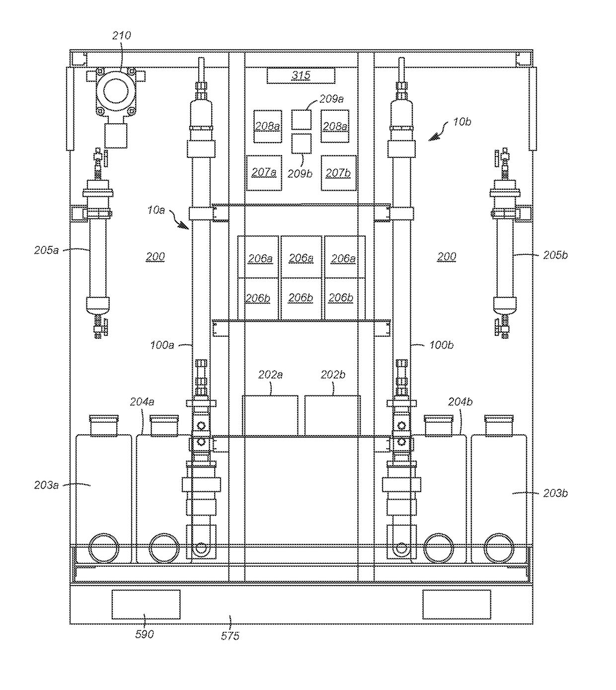
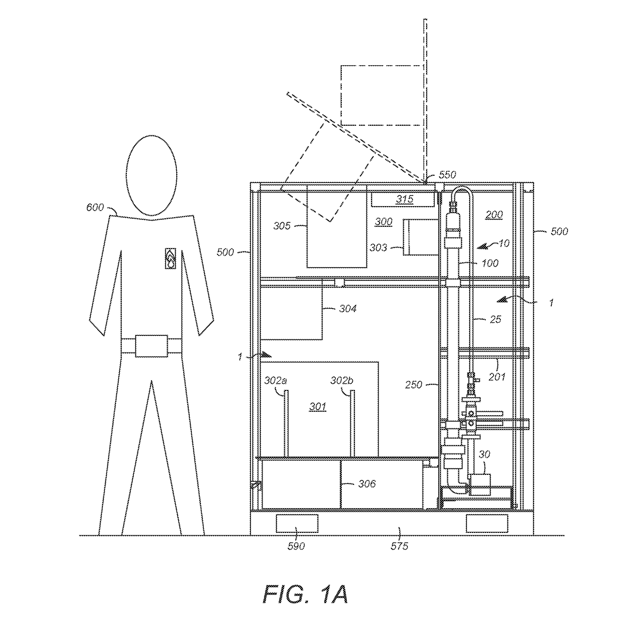
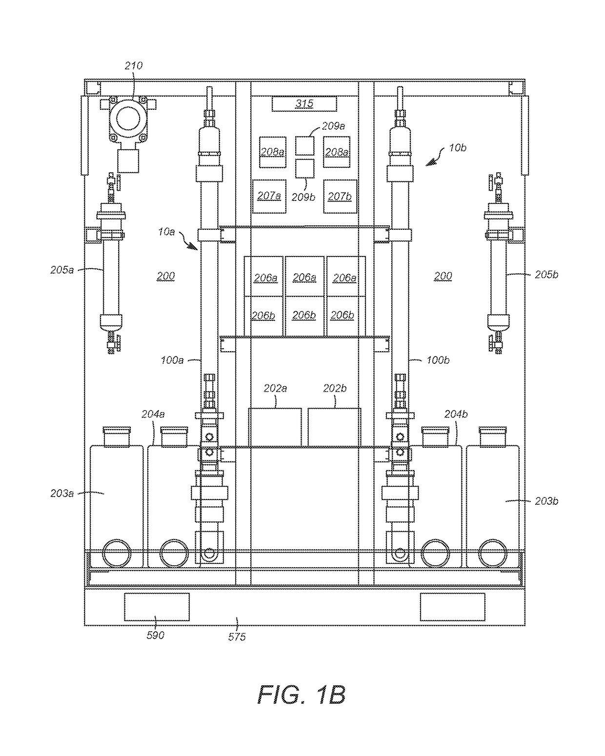
[0108]A gas testing unit was constructed, having a bioreactor section, including two circulated loop reactors (2 liters in reactor volume each). The control of C1-containing substrates (reference and test) was based on gas flow meter / controller settings, and an automatic pH compensation (control) system was included for each reactor, based on adjustment of NH4OH or other basic neutralizing agent flow. The reactor stages did not include membrane separation systems for the separation and recycle of the bacterial culture. Heat tracing and a fan were installed in the bioreactor section for reactor temperature control. Equipment in the analytical section, maintained apart from the bioreactor section using a vertical partition, included a dual column gas chromatograph (separate GC columns for gas and liquid samples) and valves / actuators to allow for automated sampling for gas analysis. The analytical section was configured for manual injection into the GC of liquid produ...

example 2

[0111]The Gas Testing unit of Example 1 was sent to a customer site to facilitate testing of the customer C1-containing substrate (test C1-containing substrate). The C1-containing gas to be tested was as industrial gas produced as a major by-product of a phosphorus production process. Typically the C1-containing as was being flared by the customer. The gas testing unit was sent to the site to determine whether the test C1-containing substrate was suitable for conversion to products by a biological conversion process.

[0112]The composition of the test C1-containing substrate is shown in table 3.

[0113]

TABLE 3Bulk CompositionKnown Contaminants (ppm)CON2CO2H2PH3H2SP2O5P472%20%1%6%1200-14000-10001000-2000300-1000

[0114]Gas clean-up of the test C1-containing substrate typically involved passing the test C1-containing substrate through an electrostatic precipitator and water scrubber. The test C1-containing substrate was further treated to remove known contaminants. The further treatment inc...


PUM

PropertyMeasurementUnit
volumeaaaaaaaaaa
heightaaaaaaaaaa
heightaaaaaaaaaa

Abstract

Apparatuses and associated methods are described for the efficient evaluation of C1-containing substrates, and especially for such evaluation conducted locally, or on-site, at a prospective facility for implementation of a biological conversion process for desired end product using a C1 carbon source. The exact composition of a given, industrial C1-containing substrate, as well as the range in composition fluctuations, are generally difficult to reproduce at a remote facility (e.g., a laboratory or a pilot-scale or demonstration-scale process), as required for the accurate prediction / modeling of commercial performance to justify large capital expenditures for commercial scale-up.

Description

FIELD OF THE INVENTION[0001]Aspects of the invention relate to apparatuses that include separate bioreactor stages for assessing the comparative performance between a test CO-containing substrate and a reference CO-containing substrate. Advantageously, such apparatuses may be housed within a container suitable for transport (e.g., to where an industrial CO-containing waste gas is produced).DESCRIPTION OF RELATED ART[0002]Environmental concerns over fossil fuel greenhouse gas (GHG) emissions have led to an increasing emphasis on renewable energy sources. As a result, ethanol is rapidly becoming a major hydrogen-rich liquid transport fuel around the world. Continued growth in the global market for the fuel ethanol industry is expected for the foreseeable future, based on increased emphasis on ethanol production in Europe, Japan, and the United States, as well as several developing nations. For example, in the United States, ethanol is used to produce E10, a 10% mixture of ethanol in g...

Claims


Application Information

Patent Timeline
Patent Type & Authority Patents(United States)
IPC IPC(8): C12Q1/02C12M1/107G01N30/88G01N30/02C12M1/34C12M3/00C12M1/00G01N30/46G01N30/00G01N30/86C12P7/06
CPCC12Q1/02C12M21/12C12M23/44C12M29/18C12M41/00C12M41/12C12M41/26C12M41/34G01N30/02G01N30/88C12M21/04Y02E50/343C12P7/065G01N30/462G01N30/8658G01N2030/0095Y02E50/30Y02E50/10
Inventor HEIJSTRA, BJORN DANIELSIMPSON, SEAN DENNISBOURDAKOS, NICHOLASBROMLEY, JASON CARLYAP, KAI-MING
Owner LANZATECH NEW ZEALAND LTD
Learn More