Laser loaded 3D micron and nano size forming process and equipment

A three-dimensional forming, micro-nano scale technology, applied in laser welding equipment, nanotechnology, nanotechnology, etc., can solve the problems that restrict the wide application of microfabrication technology

Inactive Publication Date: 2007-06-27
JIANGSU UNIV
View PDF0 Cites 17 Cited by
  • Summary
  • Abstract
  • Description
  • Claims
  • Application Information

AI Technical Summary

Problems solved by technology

[0004] However, the inherent characteristics of large batches, high efficiency, high precision, high density, short cycle, low cost, no pollution, and net shape required by the miniaturization industry restrict the wide application of the above-mentioned microfabrication technology.

Method used


Image

  • Laser loaded 3D micron and nano size forming process and equipment
  • Laser loaded 3D micron and nano size forming process and equipment

Examples


Embodiment Construction

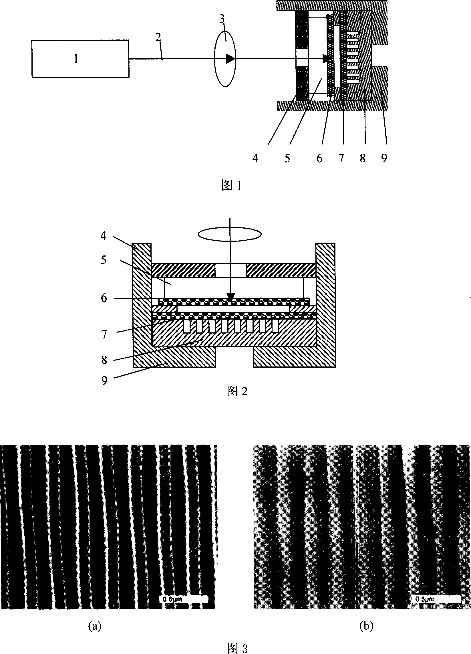
[0015] Figure 1 shows a schematic diagram of a device for laser loading to realize three-dimensional forming at the micro-nano scale. The details and implementation are described as follows:

[0016] The device for laser loading to realize micro-nano-scale three-dimensional forming consists of a laser loading system and a target clamping system. The laser loading system consists of a nanosecond pulse laser 1 and a convex lens 3. The laser beam 2 emitted by the nanosecond pulse laser 1 is focused by the convex lens and directly enters the target clamping system. The target clamping system consists of a pressing plate 4, an optical glass 5, an absorbing layer 6, a target 7, a template 8, and a target clamping device 9. The pressing plate 4 has a screw mechanism, which can be screwed into the concave hole of the target clamping device 9. Cavity, so that the optical glass 5 can be pressed together, and the target material 7 can be fastened in the concave cavity of the target mater...


PUM


Abstract

The laser loaded 3D micron and nanometer size forming process and equipment belongs to the field of MEMS processing technology and laser micro processing technology. The 3D forming process includes the following steps: grinding and polishing the two sides of target, and pressing one micron level thick aluminum film as the absorption layer and one transparent optical medium as the restraint layer onto the target; regulating ns pulse laser and optical path for focusing the laser onto the target surface and emitting single ns laser pulse to impact the target for adhesion between the target and the template. The present invention can form impacted surface with greatly raised hardness, corrosion resistance, wear resistance and fatigue strength, and may be used widely in machining key parts in MEMS. The machining process has the advantages of easy control, high machining flexibility and no pollution.

Description

technical field [0001] The invention belongs to the field of microelectromechanical system (MEMS) processing technology and laser micromachining, and particularly refers to a method and device for realizing micro-nano-scale three-dimensional forming by laser loading. Nanosecond pulsed laser radiation is used to irradiate the surface of a solid absorbing layer material to make the surface gas After melting, a high-temperature and high-pressure plasma is formed, and the rapid expansion and explosion of the plasma produces a shock wave that impacts the solid target to cause plastic deformation at the micro-nano scale. Background technique [0002] Since the IEEE Micro Robot sand Tele operators symposium held in the United States in 1987, the term micro-electromechanical system (MEMS) was first proposed. After decades of development, MEMS technology is currently used in design tools and design methods, manufacturing Great progress has been made in technology and related equipmen...

Claims


Application Information

Patent Timeline
Patent Type & Authority Applications(China)
IPC IPC(8): B82B3/00B23K26/00
Inventor 周明黄涛李保家
Owner JIANGSU UNIV
Why Eureka
Try Eureka