Flooded copper-evaporating heat-exchanging pipe for electric refrigerator set

A heat exchange tube and flooded technology, which is applied in the field of flooded copper evaporation heat exchange tubes, can solve problems such as unfavorable condensation performance and space reservation, and achieve easy nucleation and vaporization, improved heat dissipation efficiency, and accelerated vaporization process Effect

Active Publication Date: 2007-06-20
GOLDEN DRAGON PRECISE COPPER TUBE GROUP
View PDF0 Cites 12 Cited by
  • Summary
  • Abstract
  • Description
  • Claims
  • Application Information

AI Technical Summary

Problems solved by technology

There are several ways to improve the evaporation tube commonly used at present: 1) Increase the surface heat transfer area, which is generally achieved by adding fins on the outer surface of the tube or directly processing fins on the outer surface of the tube, but adding fins on the outer surface Fins usually produce thermal resistance between the fins and the outer surface of the tube, and processing fins on the outer surface is often limited by the process and the size of the tube and cannot fully meet the heat dissipation requirements; The space formed by the bubble nuclei is easy to form bubbles in the above-mentioned space. The bubbles are driven by heat to become larger when they are close to the surface of the evaporation tube. Due to the effect of the surface tension of the liquid, the bubbles can only leave the surface when they are large enough to overcome the surface tension of the liquid. Some tube surfaces have a large space to promote the formation of bubble nuclei, and the volume required for the bubbles to overcome the liquid tension also needs to be large enough, so it is not conducive to quickly taking away the heat on the surface, and it is also not conducive to quickly leaving space for new bubbles Formation; 3) At present, the transition length of the incomplete fin between the smooth surface of the evaporator tube and the surface with fins is about 60 mm, and the greater the transition length of the incomplete fin, the more incomplete fins , the more detrimental to the improvement of condensation performance

Method used


Image

  • Flooded copper-evaporating heat-exchanging pipe for electric refrigerator set
  • Flooded copper-evaporating heat-exchanging pipe for electric refrigerator set
  • Flooded copper-evaporating heat-exchanging pipe for electric refrigerator set

Examples


Embodiment Construction

[0031] The preferred embodiments of the present invention will be described in detail below in conjunction with the accompanying drawings.

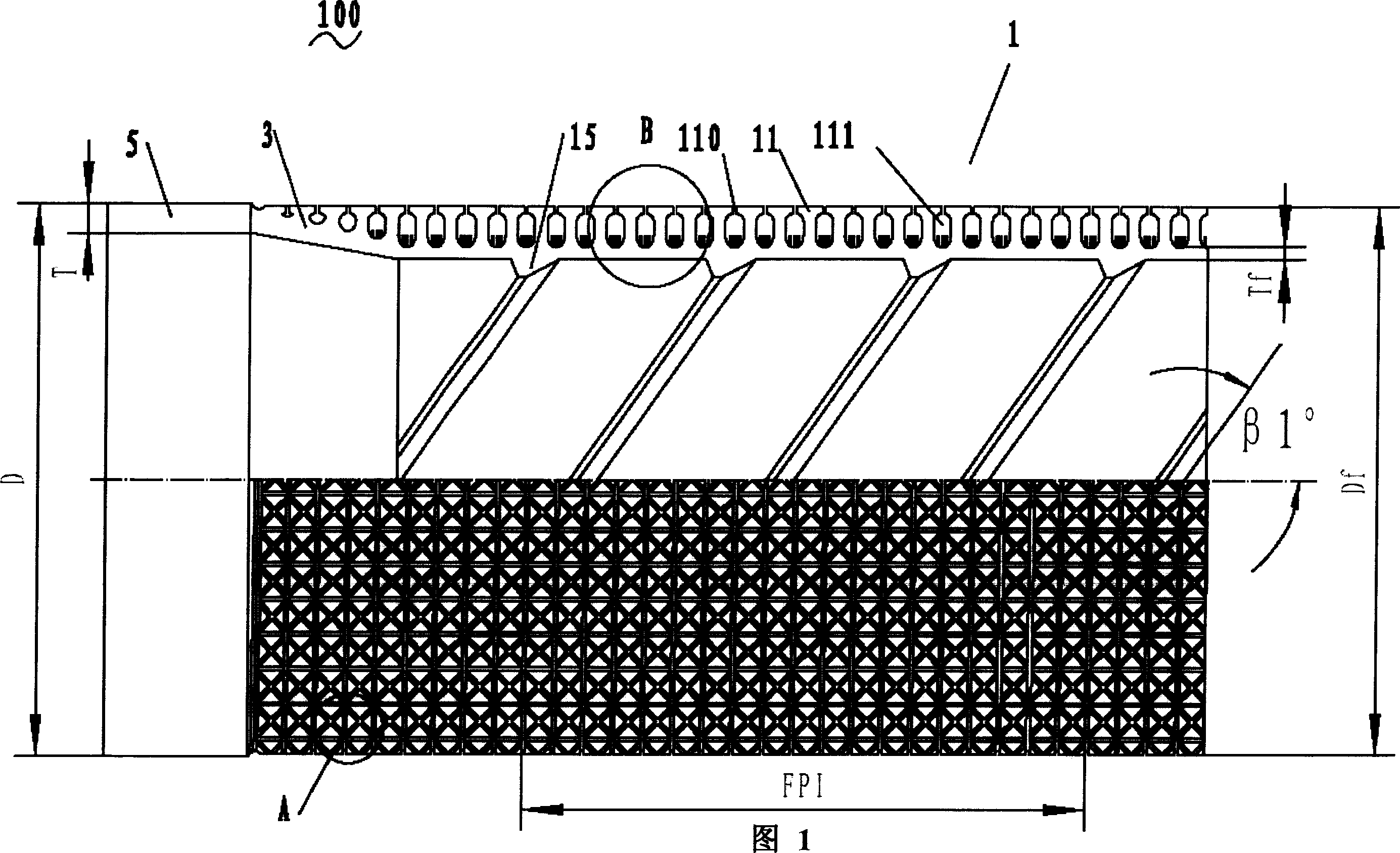
[0032] Please refer to FIG. 1, the evaporative heat exchange tube 100 of the present invention includes a fin part 1, a polished rod part 5 (only one end is shown in the figure) located at both ends of the evaporative heat transfer tube 100, and a polished rod part 5 and a finned part 1. The transition portion 3 between them is the internal teeth 15 provided on the inner surface of the evaporating heat exchange tube 100 . The diameter D of the polished rod portion 5 ranges from 12-26 mm, and the wall thickness T ranges from 0.5-0.9 mm. Preferably, the evaporation heat exchange tube 100 of the present invention is made of copper material. The present invention manufactures a flooded evaporative heat exchange tube 100 with a diameter D in the range of 12-26 mm through research on the heat exchange mechanism, forming tooling and forming proc...


PUM


Abstract

A flooded copper evaporation heat-exchange tube for electric refrigerating units comprises a polish rod pant, a fins part and a transition part for connecting the polish rod with the fins part. Between the fins is formed a single vaporization chamber and in the position extending upward from the bottom of the single vaporization chamber are disposed fins, which divide the single vaporization chamber into at least two small cavities. Between the fins of the single vaporization chamber there is an evaporation fin mouth. Because of setting several small cavities, on the base walls of the small cavities is formed the refrigerant film easily and then evaporated, and the formed bubbles escape from the evaporation fin mouth.

Description

technical field [0001] The invention relates to an evaporation heat exchange tube, in particular to a flooded copper evaporation heat exchange tube used in an electric refrigeration unit. Background technique [0002] In recent years, the rapid development of refrigeration and air-conditioning technology has promoted the continuous updating of the manufacturing technology of the two devices. Efficiency, miniaturization, light weight and replacement of new refrigerants are still the main development directions of the two devices, and the design and technical application of the evaporation tubes for the two devices are also constantly updated and developed. There are several ways to improve the evaporation tube commonly used at present: 1) Increase the heat transfer area of ​​the surface, which is generally achieved by adding fins on the outer surface of the tube or directly processing fins on the outer surface of the tube, but adding fins on the outer surface Fins usually pr...

Claims


Application Information

Patent Timeline
Patent Type & Authority Applications(China)
IPC IPC(8): F28F1/10F28F1/42
CPCF28F1/38Y10T29/49391F28F13/187F28F1/40
Inventor 郝云玉蒋强于传富赵双
Owner GOLDEN DRAGON PRECISE COPPER TUBE GROUP
Why Eureka
Try Eureka