
Coating device

A coating device and coating technology, applied in the direction of the surface coating liquid device, spray device, spray device, etc., can solve the problems of abnormal coating, inability to form a uniform resist film, etc., to reduce foreign matter, inhibit Static electricity, the effect of inhibiting the aggregation of pigments

Inactive Publication Date: 2007-05-16
TOKYO OHKA KOGYO CO LTD
View PDF3 Cites 4 Cited by
  • Summary
  • Abstract
  • Description
  • Claims
  • Application Information

AI Technical Summary

Problems solved by technology

When this pigment-dispersed resist composition is applied to a substrate, the above-mentioned foreign matter becomes a problem of abnormal coating, and a uniform resist film cannot be formed on the substrate.
[0011] Furthermore, the coating device of Patent Document 3 uses a filter to remove fine particles, and it is not a coating device for pigment-dispersed resists.
Therefore, in Patent Document 3, no attention is paid to the above-mentioned problem of aggregation caused by static electricity.

Method used


Image

  • Coating device

Examples


Embodiment

[0035] Examples in the embodiment of the present invention will be described below, but the scope of the present invention is not limited to these Examples.

[0036] In this example, the piping of a large square (corner) substrate coater (product name: TR45310, manufactured by Tokyo Ohka Kogyo Co., Ltd.) cycle. And, as the piping (10 m) used in this large square substrate coater, a PFA tube (product name: NAFLON (registered trademark) PFA-HG tube, manufactured by Nichias Co., Ltd.) as a conventional product and a conductive tube were used, respectively. tubes (using PTFE (polytetrafluoroethylene) as a material), and the pigment-dispersed resist was circulated in each tube for 1 hour.

[0037] Then, the pigment-dispersed resist composition circulating in each pipe was sampled, coated on a 550 [mm]×650 [mm] glass, and the number of foreign matter was counted for comparison. In the present embodiment, the test was carried out three times, and the average value was calculated. ...


PUM


Abstract

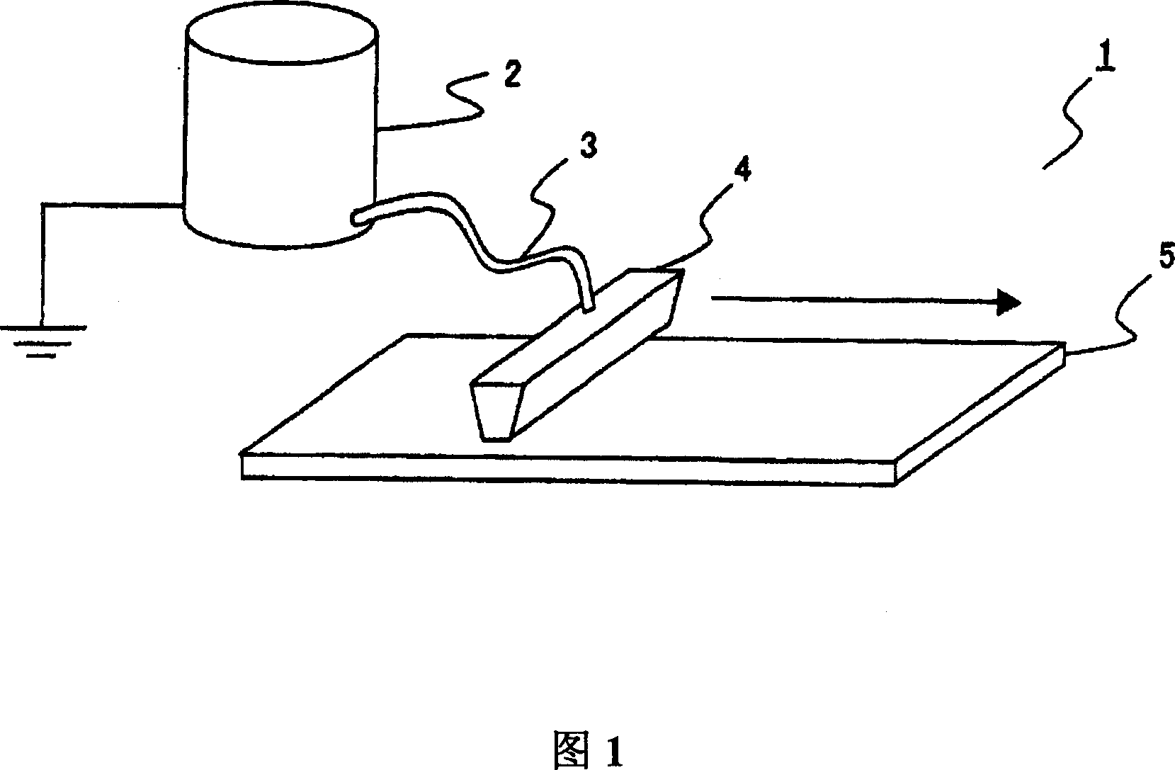
The invention provides a coating applicator for suppressing an aggregation of pigment components of a pigment-dispersed resist. The coating applicator which coats a pigment-dispersed resist solution on a processing substrate comprises a nozzle for discharging the pigment-dispersed resist solution, a coating solution supply for supplying the pigment-dispersed resist solution, and a piping composed of a conductive tube which introduces the pigment-dispersed resist solution supplied from the coating solution supply to the ozzle. Thus, when the pigment-dispersed resist solution passes through the onductive tube, an aggregation of the pigment components can be uppressed.

Description

technical field [0001] The present invention relates to a coating device for coating a coating liquid on a substrate. Background technique [0002] Conventionally, a spin coating method (spin method) is known as a representative method of applying a chemical solution on a substrate (see, for example, Patent Document 1). The spin coating method (spin coating method) refers to a method in which, when the substrate is a semiconductor wafer (hereinafter referred to as wafer), the wafer is held on a spin chuck, and a chemical solution is dripped onto the surface of the wafer from a chemical solution discharge nozzle. At the same time, the spin chuck is rotated at high speed, and the chemical solution is spread and coated on the entire surface of the wafer by centrifugal force. [0003] In addition, recently, non-spin coating methods (for example, Refer to Patent Document 2). The non-spin coating method refers to a method in which the resist nozzle is relatively moved or scanne...

Claims


Application Information

Patent Timeline
IPC IPC(8): G03F7/16
CPCB05B1/005B05C11/10B05D1/005G03F7/162H01L21/6715
Inventor 原田光治内河喜代司
Owner TOKYO OHKA KOGYO CO LTD
Learn More