
High power lithium ion cell

A lithium-ion battery, high-power technology, applied in the direction of secondary batteries, battery components, circuits, etc., can solve the problems of inability to ensure effective control of battery temperature, hidden dangers of safety and cycle life, and overall temperature rise of the battery. It achieves the effects of good high-rate discharge performance, effective control of battery temperature, and improved safety and cycle life

Active Publication Date: 2007-04-18
CHINA ELECTRONIC TECH GRP CORP NO 18 RES INST +1
View PDF1 Cites 29 Cited by
  • Summary
  • Abstract
  • Description
  • Claims
  • Application Information

AI Technical Summary

Problems solved by technology

However, when a commercial lithium-ion battery is discharged at a rate of 2C, it can only discharge about 80% of its nominal capacity, and it cannot be discharged at a rate of 10C. The main reason is that the internal resistance is too large, especially when it is discharged at a high current. , tabs, etc. are seriously heated, and the overall temperature of the battery rises excessively, causing major hidden dangers in terms of safety and cycle life
Patent No. 02295729.4 square lithium-ion secondary battery discloses that the positive plate and the negative plate of the battery are composed of the main part of the coating layer that continuously carries the active material and the non-coating layer part that is integrated with the positive and negative plates. Compared with high-power lithium-ion batteries, it reduces the internal resistance and improves the rate discharge performance, but it is only suitable for square batteries, and it cannot guarantee that the battery temperature can be effectively controlled when the battery is discharged at high power.

Method used


Image

  • High power lithium ion cell
  • High power lithium ion cell
  • High power lithium ion cell

Examples


Embodiment 1

[0030] Preparation of positive electrode:

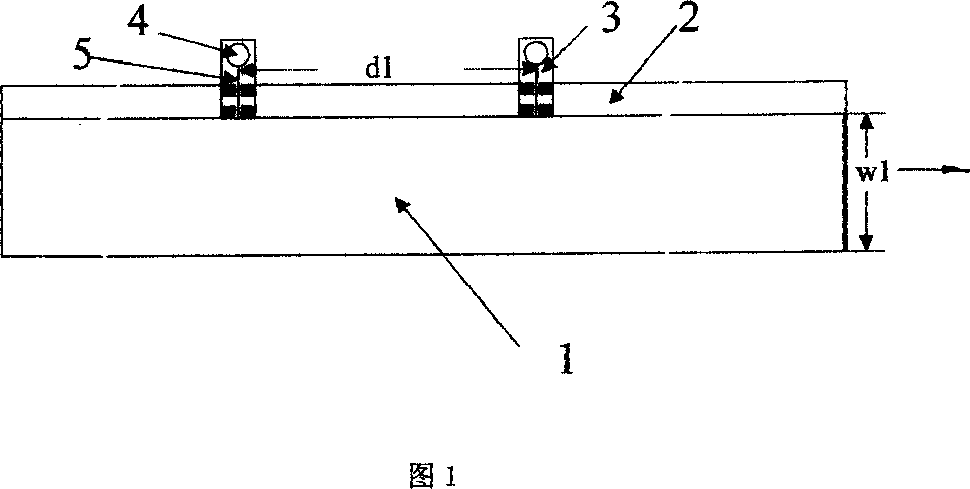
[0031] Weigh 93wt% LiCoO of the positive active material 2 , N-methyl-2-pyrrolidone (NMP) solution of polyvinylidene fluoride (PVdF) adhesive and make the content of PVdF be 4.5wt%, as the conductive material 2.5wt% (VGCF), the three are mixed Form the positive electrode mixture, add NMP to the mixture to prepare a paste with a mixer, and then apply the paste evenly and continuously to both sides of the aluminum foil with a thickness of 20 μm, the width of the coating film is 220 mm, and leave a layer on the front and back of one side of the aluminum foil. There is a 20mm blank, and after drying and rolling, cut off the opposite side of the 20mm blank (without leaving a blank) to obtain a positive electrode plate with a coating width of 200mm and a blank of 20mm width. Coating weight is 22mg / cm 2 .

[0032] Preparation of negative electrode:

[0033] Be that the mesophase carbon microsphere MCMB of 60% by weight, the flaky graphi...

Embodiment 2

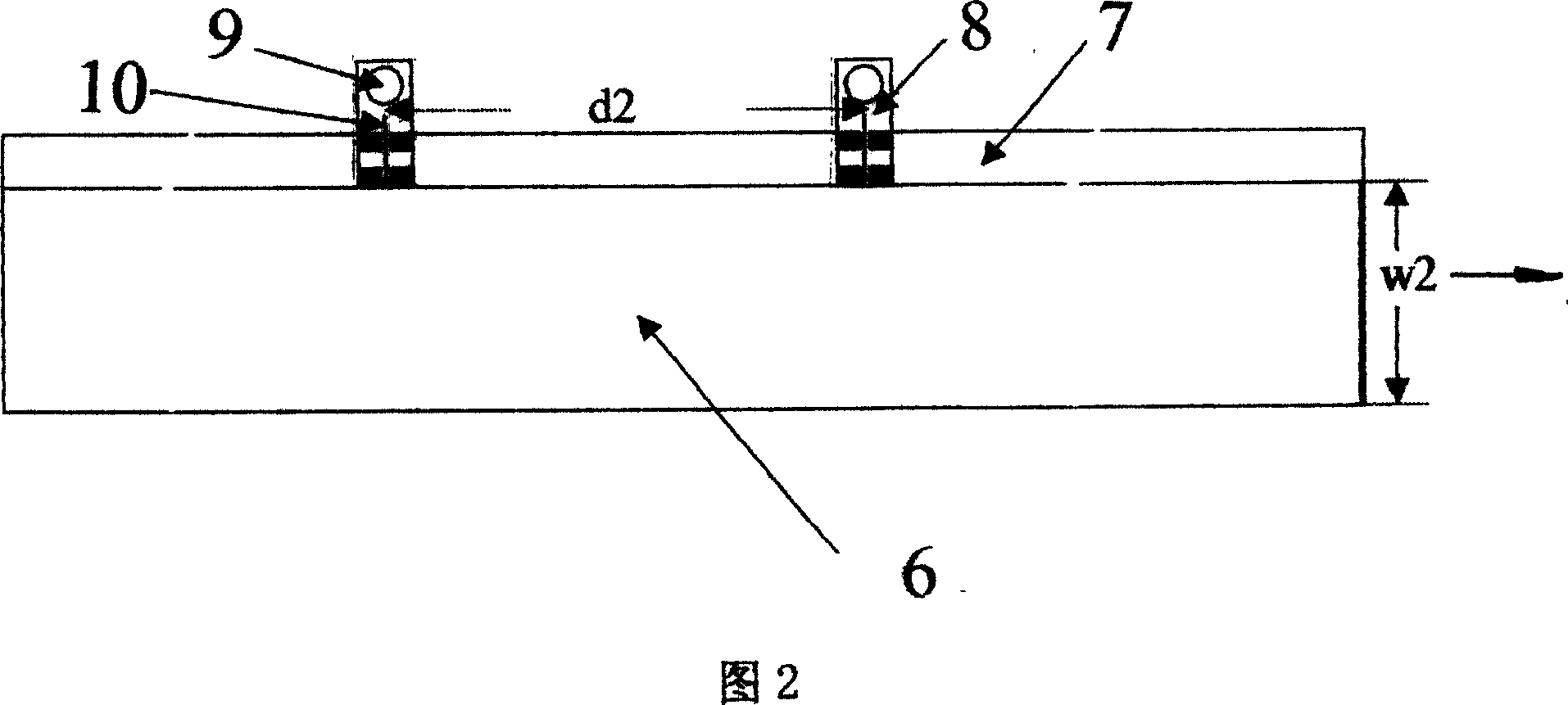
[0044] Except that d1 and d2 were changed to 300 mm, everything else was the same as that of Example 1 to produce battery A2 of the present invention, and the measurement results are also listed in Table 1.

Embodiment 3

[0046]Except that d2 was changed to 500 mm, the battery A3 of the present invention was produced in the same manner as in Example 1, and the measurement results thereof are also listed in Table 1.


PUM

PropertyMeasurementUnit
Widthaaaaaaaaaa
Widthaaaaaaaaaa
Thicknessaaaaaaaaaa

Abstract

The invention belongs to a high power Li ion battery, comprising anode, cathode, diaphragm and nonaqueous electrolyte, where anode and cathode coatings containing active materials are continuous coatings, one side of each of the anode and cathode in the coiling direction has a current collector margin where anode and cathode ears are arranged. And it is characterized in that: anode ear section area S1, anode ear distance d1 and anode coating width w1 meet: 1*10-5 H01M 10 / 40 H01M 4 / 02 H01M 4 / 64 2 9 1 2005 / 10 / 14 1949580 2007 / 4 / 18 100433440 2008 / 11 / 12 2008 / 11 / 12 2008 / 11 / 12 No.18 Inst., China Electronic Science and Technology Group Corp. Tianjin 300381 Liu Xingjiang Zhang Yao Zhu Guangyan Yang Kai Yu Jinhan Wu Bincheng lifeng 12101 The Patent Agency of Tianjin Machine-building Industry Administering Bureau No.15 Jinzhong Bridge Street, Hongqiao, District, Tianjin 300091

Description

technical field [0001] The invention belongs to the technical field of lithium ion batteries, in particular to a high-power lithium ion battery. Background technique [0002] Compared with traditional secondary batteries such as lead-acid, nickel-cadmium, and nickel-metal hydride, lithium-ion batteries have been widely used in electronic appliances such as mobile phones, notebook computers, and cameras due to their high specific energy and low self-discharge. [0003] Currently known low-power lithium-ion batteries are mainly composed of a negative plate with a discontinuous coating, a positive plate with a discontinuous coating, an electrolyte, and a diaphragm interposed between the positive and negative plates to prevent short circuits. The negative plate is composed of a negative electrode current collector and a carbonaceous material that intercalates / releases lithium ions; the positive electrode plate is composed of a positive electrode current collector and a composite...

Claims


Application Information

Patent Timeline
IPC IPC(8): H01M10/40H01M4/02H01M4/64H01M10/0525H01M50/533H01M50/534
CPCY02E60/122Y02E60/10
Inventor 刘兴江张遥朱广焱杨凯喻津汉吴滨成
Owner CHINA ELECTRONIC TECH GRP CORP NO 18 RES INST
Learn More