Chemical reaction apparatus utilizing microwave
A chemical reaction and microwave technology, applied in chemical/physical/physical-chemical stationary reactors, chemical/physical/physical-chemical processes using energy, microwave heating, etc. problem, to achieve the effect of precise control of the reaction temperature
- Summary
- Abstract
- Description
- Claims
- Application Information
AI Technical Summary
Problems solved by technology
Method used
Image
Examples
Embodiment 1
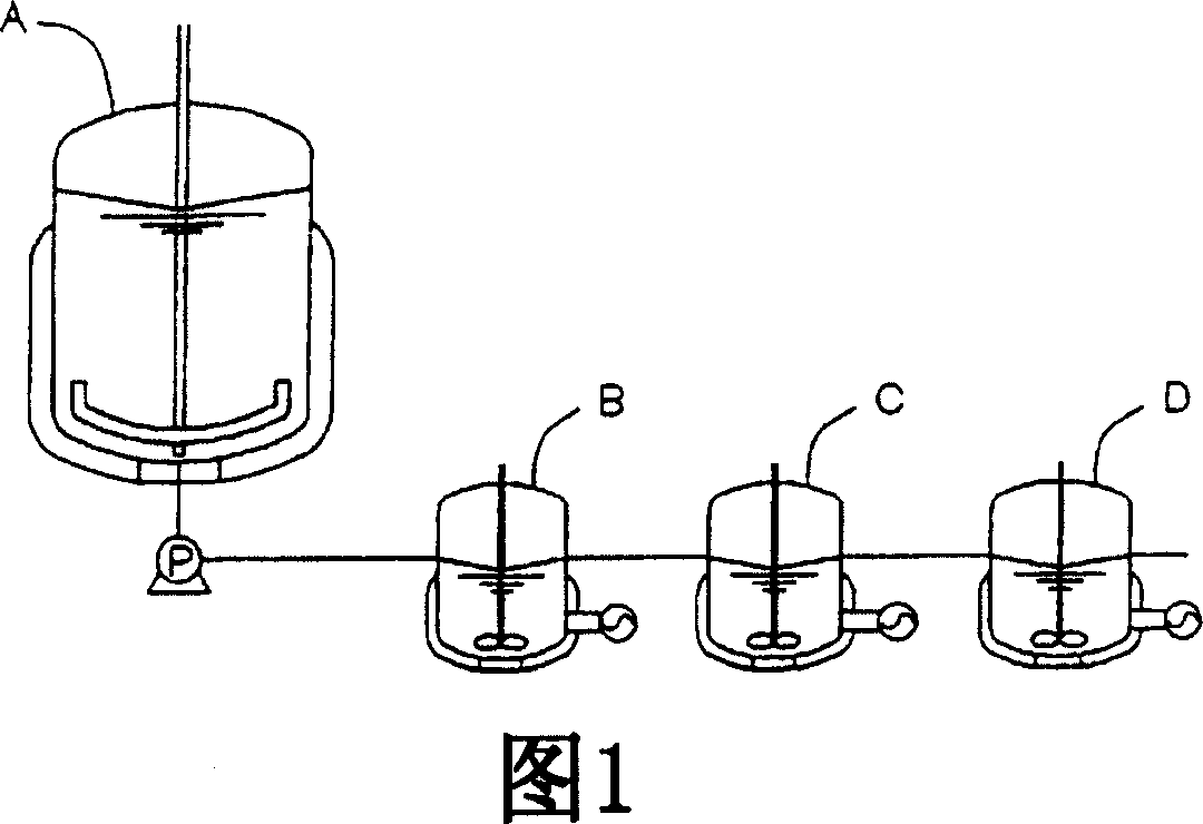
[0095] Fig. 1 is an example of the reaction apparatus of the present invention, and is a conceptual diagram of a microwave chemical reaction apparatus capable of three-stage continuous reaction having a preliminary vessel.
[0096] The composition of this reaction unit comprises:
[0097] A preparatory container (hereinafter referred to as a raw material dissolution tank) (A) for mixing, heating, dissolving or melting the reaction raw materials (hereinafter referred to as the reaction substrate conveniently), and
[0098] Carry out the chemical reaction vessel (hereinafter referred to as the microwave reaction tank conveniently) (B) of the first-stage reaction, and
[0099] Next, the microwave reaction tank (C) that undertakes most of the reactions as the second stage, and
[0100] Further carry out the microwave reaction tank (D) of the third stage of finishing reaction.
[0101] Hereinafter, the preparation of 3,3'-diallyloxy-4,4'-dihydroxydiphenyl sulfone (abbreviated as ...
Embodiment 2
[0133] The microwave reaction tank shown in Figure 5 (with an effective volume of 1.5 liters) was connected to 3 tanks (B, C, D) as shown in Figure 1 to perform continuous reaction.
[0134] Before starting the continuous reaction, perform the following preparations in advance.
[0135] Put a predetermined amount of powdery raw material 4,4'-diallyloxydiphenyl sulfone (AOPS) into the raw material dissolving tank (A) through the raw material supply hole, circulate the heat medium in the shell, and heat the temperature in the container to AOPS is melted at 160°C to 180°C above the melting point of AOPS (145°C). Then continue to stir to replace the gas in the container with nitrogen, and maintain an oxygen-free state. And, at the same time, preheat the temperature of the connection pipe (21) pipeline of the extraction nozzle (5), quantitative pump (6), and microwave reaction tank to the preferred temperature of 160°C to 180°C for liquid delivery, and maintain this temperature. ...
Embodiment 3
[0142] A batch reaction was performed using one microwave reaction tank (B) shown in FIG. 5 connected to the raw material dissolution tank (A).
[0143] Before starting the batch reaction, as in Example 2, AOPS was melted, preheated, and replaced with nitrogen in advance.
[0144] Immediately after the preparation, 1.0 kg of molten raw material AOPS is supplied to the microwave reaction tank (B), and nitrogen gas is introduced into the container to maintain an oxygen-free state. Next, a heat medium (160° C. to 190° C.) is circulated in the casing while microwaves are irradiated. The temperature in the microwave irradiation reaction tank was raised from 160°C to 240°C at a rate of 8°C / min, and from 240°C to 260°C at a rate of 1°C / min., and kept at 260°C for 3 minutes for batch reaction, and the reaction ended Finally, open the take-out valve at the bottom of the reaction tank, take out the reaction solution, take a sample and analyze it by liquid chromatography. The results a...
PUM
 Abstract
Description
Claims
Application Information
 - R&D Engineer
- R&D Manager
- IP Professional
- Industry Leading Data Capabilities
- Powerful AI technology
- Patent DNA Extraction
Browse by: Latest US Patents, China's latest patents, Technical Efficacy Thesaurus, Application Domain, Technology Topic, Popular Technical Reports.
© 2024 PatSnap. All rights reserved.Legal|Privacy policy|Modern Slavery Act Transparency Statement|Sitemap|About US| Contact US: help@patsnap.com


