
In situ regenerating method and device for medium blocking discharging plasma active carbon

A technology of dielectric barrier discharge and plasma, applied in separation methods, filter regeneration, chemical instruments and methods, etc., can solve the problems of activated carbon loss, high cost, secondary pollution, etc., achieve less activated carbon loss, short regeneration time, The effect of high regeneration efficiency

Inactive Publication Date: 2007-01-24
DALIAN UNIV OF TECH
View PDF0 Cites 26 Cited by
  • Summary
  • Abstract
  • Description
  • Claims
  • Application Information

AI Technical Summary

Problems solved by technology

The thermal regeneration method usually requires external heating, which is costly, and at the same time, the activated carbon will lose 5%-10% after regeneration
The wet oxidation regeneration method may produce more toxic intermediate products for some refractory organic substances, causing secondary pollution
Therefore, people consider the use of high-efficiency catalysts to regenerate activated carbon by catalytic wet oxidation, but this method requires high equipment, inconvenient operation, and has problems such as high operation and maintenance costs.
The electrochemical regeneration method can be regenerated on site, but it will also cause a certain degree of secondary pollution and activated carbon loss, and cannot fundamentally solve the pollution problem
The solvent regeneration method is too specific, often a solvent can only desorb some pollutants, and the expensive solvent needs to be recycled, which is costly
However, there are problems such as long regeneration cycle in biological regeneration.
The supercritical fluid regeneration method also has problems such as high equipment requirements

Method used


Image

  • In situ regenerating method and device for medium blocking discharging plasma active carbon
  • In situ regenerating method and device for medium blocking discharging plasma active carbon
  • In situ regenerating method and device for medium blocking discharging plasma active carbon

Examples


Embodiment Construction

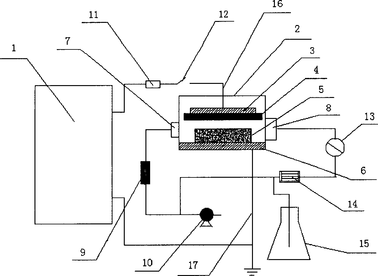
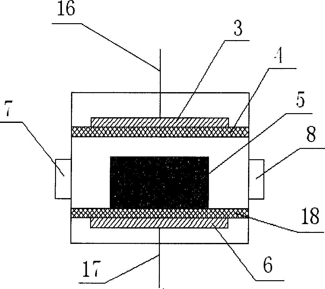
[0049] The device used in this example is figure 1 As shown, the frequency of the alternating high-voltage power supply 1 is 50HZ, the effective voltage range is 0-50kV, and the rated power is 1kW. The reactor shell is made of plexiglass, and the shape is a cuboid of 400mm×450mm×120mm. In this example, the discharge electrode and discharge medium are placed and selected figure 2 The high-voltage electrode 3 is a stainless steel plate of 200mm×200mm×4mm, the low-voltage electrode 6 is a stainless steel plate of 350mm×400mm×4mm, the quartz glass plate of 300mm×300mm×2mm is used as the high-voltage discharge medium 4, and the distance between the two electrode plates is 22mm , containing 2mm discharge medium; the gas is air; the activated carbon used is columnar coal-based activated carbon with a diameter of 3mm and an average length of 10mm, the thickness of the activated carbon is 9mm, and the moisture content of the activated carbon to be regenerated is 16%; in addition, thi...


PUM

PropertyMeasurementUnit
Thicknessaaaaaaaaaa
Particle size rangeaaaaaaaaaa
Diameteraaaaaaaaaa

Abstract

The in situ active carbon regenerating method and apparatus with medium blocking discharge plasma belongs to the field of chemical adsorbing separation and pollutant controlling technology. Under atmospheric pressure, low temperature unbalanced plasma generated through medium blocking discharge is used to in situ regenerate active carbon with adsorbate filled between the discharge electrodes under the action of high activity matter, ultraviolet and high energy electron bombardment, etc. The in situ active carbon regenerating apparatus consists of high voltage AC source, reactor and auxiliary device mainly. The present invention has the advantages of high regeneration efficiency, short regeneration period, no secondary pollution, no need of post-treatment, low active carbon loss, etc; and is suitable for active carbon regeneration mainly.

Description

technical field [0001] The invention belongs to the technical field of chemical adsorption separation and pollutant control. In particular, it relates to a dielectric barrier discharge plasma activated carbon in-situ regeneration method and device. The present invention combines new electrical technology, chemical adsorption and separation engineering and environmental engineering, and uses high-speed electrons, ozone, ultraviolet rays, active chemical substances, etc. generated by dielectric barrier discharge to comprehensively degrade waste water, waste gas, etc. adsorbed on activated carbon through physical and chemical effects. Pollutants, so that the activated carbon can be regenerated and activated in situ. Background technique [0002] Activated carbon is a hydrophobic non-polar carbon adsorbent made of coal, charcoal, coconut shell, etc., after high-temperature carbonization and activation. It has a highly developed pore structure and a large specific surface area. ...

Claims


Application Information

Patent Timeline
IPC IPC(8): B01J20/34B01J20/20
Inventor 李杰屈广周吴彦
Owner DALIAN UNIV OF TECH
Learn More