
Gasoline particulate filter regeneration and diagnostics

a technology of particulate filter and gasoline, which is applied in the direction of machines/engines, output power, electric control, etc., can solve the problems of short opportunity for injected fuel, increased oxidation rate of soot in the particulate filter, and forming of particles in engine exhaust, etc., to reduce transient air-fuel disturbance, improve engine performance, and reduce the effect of soot emissions

Active Publication Date: 2012-12-11
FORD GLOBAL TECH LLC
View PDF9 Cites 21 Cited by
  • Summary
  • Abstract
  • Description
  • Claims
  • Application Information

AI Technical Summary

Benefits of technology

The patent describes a method for regenerating a particulate filter in gasoline engines. The method involves monitoring the air-fuel ratio downstream of the particulate filter for changes in exhaust air-fuel oscillations, and enhancing the air-fuel ratio to improve regeneration efficiency and reduce regeneration time. The method also involves introducing secondary air to the particulate filter to aid in regeneration without disturbing the processing of engine exhaust gases in the upstream emissions control device. By monitoring changes in temperature and oxygen sensor lambda, the method ensures accurate introduction of secondary air and improves particulate filter regeneration efficiency and reduces regeneration time.

Problems solved by technology

However, at higher engine speeds and higher engine loads, particulates may form in engine exhaust.
Specifically, there may be only a short opportunity for the injected fuel to vaporize and form a homogenous mixture before combustion is initiated.
Accurate introduction of secondary air may increase the oxidation rate of soot in the particulate filter.

Method used


Image

  • Gasoline particulate filter regeneration and diagnostics
  • Gasoline particulate filter regeneration and diagnostics
  • Gasoline particulate filter regeneration and diagnostics

Examples


Embodiment Construction

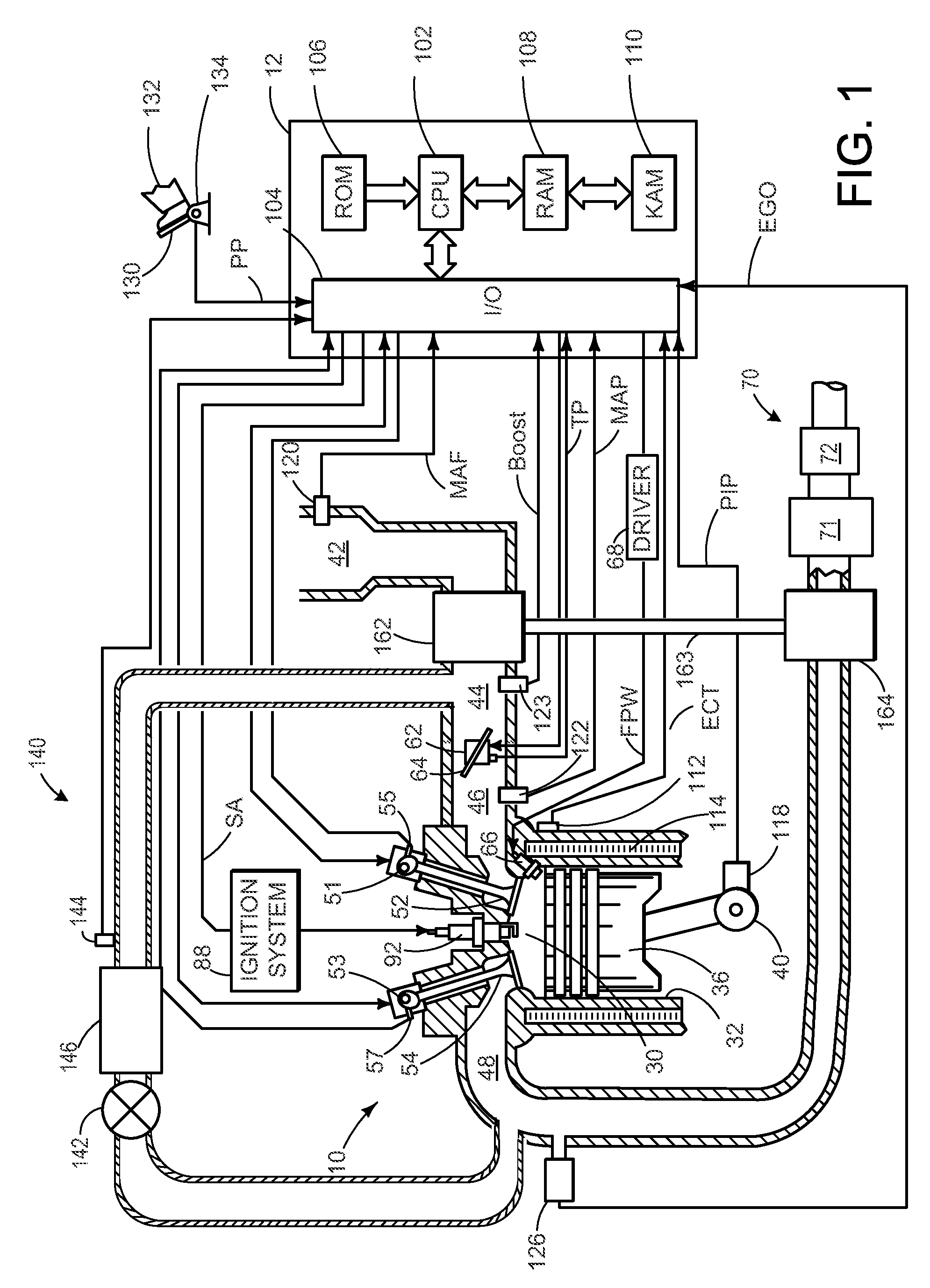
[0033]FIG. 1 is a schematic diagram showing one cylinder of multi-cylinder engine 10, which may be included in a propulsion system of an automobile. Engine 10 may be controlled at least partially by a control system including controller 12 and by input from a vehicle operator 132 via an input device 130. In this example, input device 130 includes an accelerator pedal and a pedal position sensor 134 for generating a proportional pedal position signal PP. Combustion chamber (i.e., cylinder) 30 of engine 10 may include combustion chamber walls 32 with piston 36 positioned therein. Piston 36 may be coupled to crankshaft 40 so that reciprocating motion of the piston is translated into rotational motion of the crankshaft. Crankshaft 40 may be coupled to at least one drive wheel of a vehicle via an intermediate transmission system. Further, a starter motor may be coupled to crankshaft 40 via a flywheel to enable a starting operation of engine 10.

[0034]Combustion chamber 30 may receive inta...


PUM


Abstract

A method for operating a spark-ignition engine having a three-way catalyst and a particulate filter downstream thereof, comprising: oscillating an exhaust air-fuel ratio entering the particulate filter to generate air-fuel ratio oscillations downstream of the particulate filter, while increasing exhaust temperature; when the downstream oscillations are sufficiently dissipated, enleaning the exhaust air-fuel ratio entering the particulate filter; and reducing the enleanment when an exhaust operating parameter is beyond a threshold amount.

Description

CROSS-REFERENCE TO RELATED APPLICATION[0001]This application claims priority to U.S. Provisional Patent Application Ser. No. 61 / 246,930, entitled “GASOLINE PARTICULATE FILTER REGENERATION AND DIAGNOSTICS,” filed Sep. 29, 2009, the disclosure of which is hereby incorporated by reference in its entirety and for all purposes.BACKGROUND AND SUMMARY[0002]Recently, direct injection gasoline engines have been shown to improve engine performance and to reduce transient air-fuel disturbances that may be caused by fuel adhering to the intake manifold and ports of an engine. However, at higher engine speeds and higher engine loads, particulates may form in engine exhaust. Under some conditions, formation of the particulates may be related to the short amount of time between when fuel is injected to the cylinder and when combustion is initiated by a spark plug. Specifically, there may be only a short opportunity for the injected fuel to vaporize and form a homogenous mixture before combustion i...

Claims


Application Information

Patent Timeline
Patent Type & Authority Patents(United States)
IPC IPC(8): F01N3/00
CPCF01N3/023F01N3/32F01N9/00F02B37/00F02D41/029F02M25/0707F02M25/0709F02M25/0718F02D19/0655F01N2560/025F01N2560/06F02D13/0215F02D41/0055F02D41/1439F02M25/0732F02M25/0752F02M25/0754F02M25/0755Y02T10/36Y02T10/144Y02T10/47Y02T10/22F02M26/46F02M26/05F02M26/06F02M26/15F02M26/24F02M26/01F02M26/47Y02T10/12Y02T10/30Y02T10/40
Inventor RUONA, WILLIAM CHARLESVAN NIEUWSTADT, MICHIEL J.
Owner FORD GLOBAL TECH LLC
Learn More