Ultrasonic electrolysis compounding micro processing method and device
A microfabrication and electrical machining technology, applied in the direction of electric processing equipment, metal processing equipment, circuits, etc., can solve problems such as unsustainability, efficiency, precision reduction, tool loss, etc.
- Summary
- Abstract
- Description
- Claims
- Application Information
AI Technical Summary
Problems solved by technology
Method used
Image
Examples
example 1
[0034] Example 1: φ0.20mm micro-axis cathode processes micro-holes on YT cemented carbide
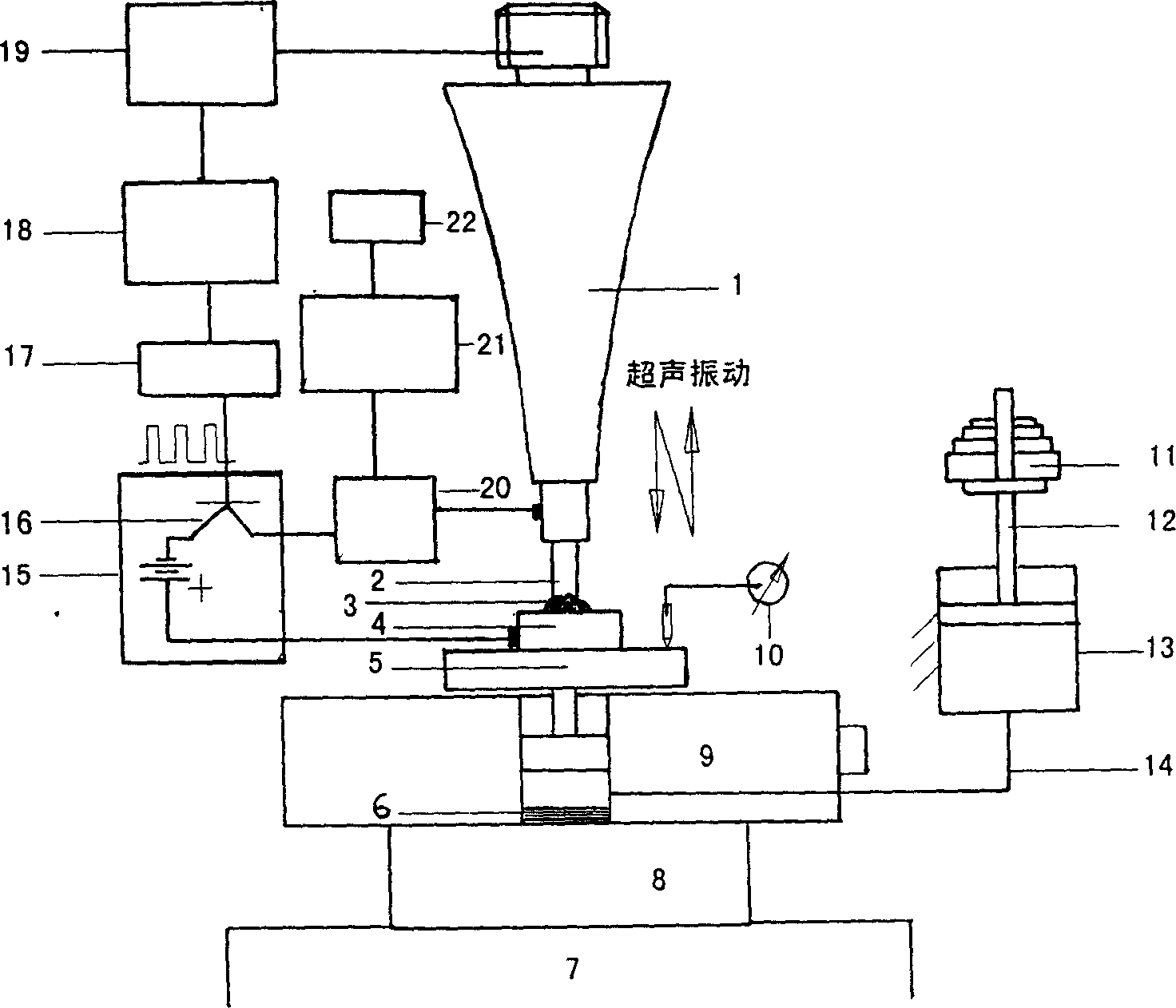
[0035] The processing process starts with the cathode production: the horn is processed by multi-axis linkage numerical control machining method, the shape of the cathode of the tool is preliminarily processed, and the connecting thread of the two is finished after finishing, and the coupling is performed with castor oil; after the horn and the cathode are connected with precision threads , and then use the micro-combined electric machining method for finishing; on the four-axis linkage precision EDM machine tool, the sheet electrode is used to feed in the x-direction and y-direction, and it is equipped with the spindle rotation micro-discharge method, which can process the axial without taper. φ0.20mm fine shaft cathode.
[0036] Fix the YT cemented carbide material on the micro-table insulated from the device with double-sided adhesive, connect the fine cathode and the horn after fini...
example 2
[0042] Example 2: Using a φ3.0mm cylindrical cathode with a φ0.60mm inner hole to process a fine shaft on a YG cemented carbide
[0043] As above, the cathode is first produced in the processing process, and the horn is processed by multi-axis linkage numerical control machining method. On the precision electric discharge machine tool, the chip electrode is fed in the x direction and the y direction, and it is equipped with the spindle rotating fine discharge method, which can process the φ3.0mm fine shaft cathode without taper; the φ0.60mm inner hole at the end of the cathode can be made The fine shaft slightly smaller than φ0.60mm is used as the electrode for electrical discharge machining again;
[0044] Adopt DC voltage 2V, abrasive 1600# silicon carbide; static pressure 0.80N; abrasive suspension concentration 20%; electrolyte is 4% sodium nitrate aqueous solution, use φ3.0mm with φ0.60mm inner hole on hard alloy YG15 The cylindrical cathode is processed by ultrasonic el...
example 3
[0048] Example 3 Machining a cross rib cube structure on cemented carbide with a cross groove with a width of 0.2×0.4mm
[0049] In the same way: the machining process starts with the cathode production: the horn is processed by the multi-axis linkage numerical control machining method, the shape of the cathode of the tool is preliminarily processed, and the connecting thread of the two is finished by finishing machining; after the horn and the cathode are connected with threads, the The method of fine combination electric machining is used for finishing; on the four-axis linkage precision electric discharge machine tool, the sheet electrode is used to feed in x direction and y direction, and it is equipped with the spindle rotating fine discharge method, which can process φ3.0mm without taper in the axial direction. The micro-axis cathode, with a width of 0.2×0.4mm, is precisely processed by slow wire cutting.
[0050] Using pulse voltage with amplitude 3V, frequency 5000HZ, ...
PUM
| Property | Measurement | Unit |
|---|---|---|
| Surface roughness | aaaaa | aaaaa |
| The average diameter | aaaaa | aaaaa |
| Surface roughness | aaaaa | aaaaa |
Abstract
Description
Claims
Application Information
 - R&D
- Intellectual Property
- Life Sciences
- Materials
- Tech Scout
- Unparalleled Data Quality
- Higher Quality Content
- 60% Fewer Hallucinations
Browse by: Latest US Patents, China's latest patents, Technical Efficacy Thesaurus, Application Domain, Technology Topic, Popular Technical Reports.
© 2025 PatSnap. All rights reserved.Legal|Privacy policy|Modern Slavery Act Transparency Statement|Sitemap|About US| Contact US: help@patsnap.com


