Discharge surface treatment electrode, process for producing discharge surface treatment electrode, discharge surface treatment apparatus and discharge surface treatment method
A technology of surface treatment and manufacturing method, which is applied in the direction of transportation and packaging, coating, metal material coating technology, etc., and can solve problems such as brittleness and weak particle bonding
- Summary
- Abstract
- Description
- Claims
- Application Information
AI Technical Summary
Problems solved by technology
Method used
Image
Examples
Embodiment approach 1
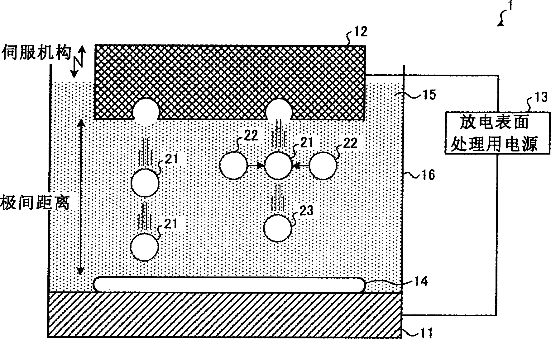
[0053] First, the outline of the discharge surface treatment method and its apparatus used in the present invention will be described. figure 2 It is a figure which shows the outline of the discharge surface treatment performed by the discharge surface treatment apparatus. The discharge surface treatment device 1 consists of a workpiece (hereinafter referred to as workpiece) 11 to form a coating 14, a discharge surface treatment electrode 12 for forming a coating on the surface of the workpiece 11, and the workpiece 11 and the discharge surface treatment. The electrodes 12 are electrically connected, and constitute a discharge surface treatment power source 13 that supplies a voltage to both to generate an arc therebetween. When the discharge surface treatment is performed in a liquid, a processing tank 16 is provided so that the gap between the workpiece 11 and the portion of the discharge surface treatment electrode 12 facing the workpiece 11 is filled with a processing liq...
Embodiment approach 2
[0078] In this Embodiment 2, the case where the electrode for discharge surface treatment is manufactured using several types of powders as an electrode material is demonstrated.
[0079] Table 2 is a table showing the relationship between the electrode material, the particle size of the powder of the electrode material, the hardness of the powder of the electrode material, and the hardness fluctuation of the electrode.
[0080]
make up
No
Electrode material
particle size
(μm)
powder
hardness fluctuation
○: No fluctuation
△: slightly fluctuating
×: There are fluctuations
1
TiC+Ti
small(2)+small(3)
hard + soft
○
2
Cr 2 o 3 +Cr
Small (L6)+Large (10)
hard + soft
○
3
CBN+ Streite Carbide
1
Big(6)+Big(6)
hard+medium
×
4
Cr 2 o 3 + Ste...
Embodiment approach 3
[0090] As described in Embodiments 1 and 2, in order to manufacture an electrode having uniform hardness, the powder constituting the electrode must have a predetermined particle diameter. For example, in the case of forming a coating having lubricity and corrosion resistance in a high-temperature environment by discharge surface treatment, in order to manufacture an electrode with uniform hardness, it is necessary to manufacture the electrode with a powder having a particle size of 3 μm or less. However, powders with a particle size of 3 μm or less are commercially available in limited materials, and powders with a particle size of 3 μm or less are not available on the market for various materials of the coating film formed on the workpiece surface. For example, WC powder with an average particle diameter of about 1 μm is widely distributed in the market and can be obtained easily and cheaply, but it is difficult to obtain other powders. Therefore, it is impossible to manufac...
PUM
| Property | Measurement | Unit |
|---|---|---|
| particle diameter | aaaaa | aaaaa |
| particle size | aaaaa | aaaaa |
| particle diameter | aaaaa | aaaaa |
Abstract
Description
Claims
Application Information
 - R&D
- Intellectual Property
- Life Sciences
- Materials
- Tech Scout
- Unparalleled Data Quality
- Higher Quality Content
- 60% Fewer Hallucinations
Browse by: Latest US Patents, China's latest patents, Technical Efficacy Thesaurus, Application Domain, Technology Topic, Popular Technical Reports.
© 2025 PatSnap. All rights reserved.Legal|Privacy policy|Modern Slavery Act Transparency Statement|Sitemap|About US| Contact US: help@patsnap.com


