Battery
A battery and electrolyte technology, applied in the direction of lithium batteries, battery electrodes, secondary batteries, etc., can solve the problems of electrolyte easy to decompose cycle characteristics, high current density, low current density, etc., to improve cycle characteristics, inhibit decomposition reactions, high effect Effect
- Summary
- Abstract
- Description
- Claims
- Application Information
AI Technical Summary
Problems solved by technology
Method used
Image
Examples
no. 1 approach
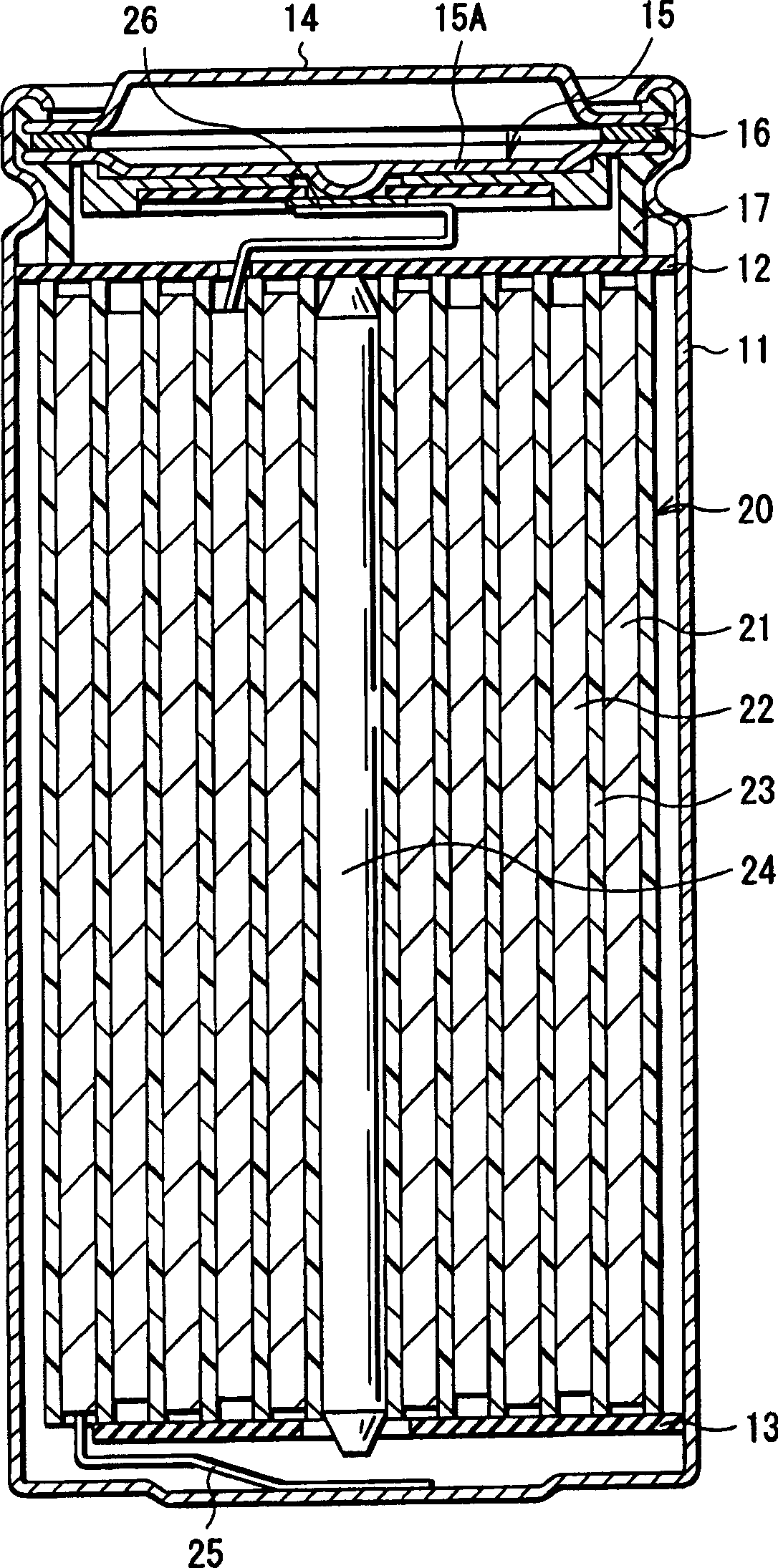
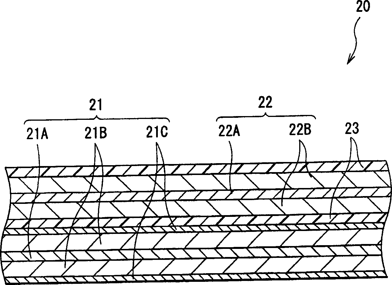
[0023] figure 1 A cross-sectional structure of a secondary battery according to a first embodiment of the present invention is shown. This secondary battery is a so-called cylindrical battery, and has a spirally wound electrode body 20 in which, inside a battery case 11 having an approximately hollow cylindrical shape, a strip-shaped negative electrode 21 and a strip-shaped positive electrode 22 are laminated with a separator 23 in between and wound. around. The battery case 11 is made of, for example, nickel-plated iron. One end of the battery case 11 is closed, and the other end thereof is opened. Inside the battery case 11 , a pair of insulating plates 12 and 13 are arranged vertically to the wound peripheral surface, respectively, so that the spirally wound electrode body 20 is sandwiched between the insulating plates 12 and 13 .
[0024] At the open end of the battery case 11 , a battery cover 14 , a safety valve mechanism 15 provided inside the battery cover 14 , and ...
no. 2 approach
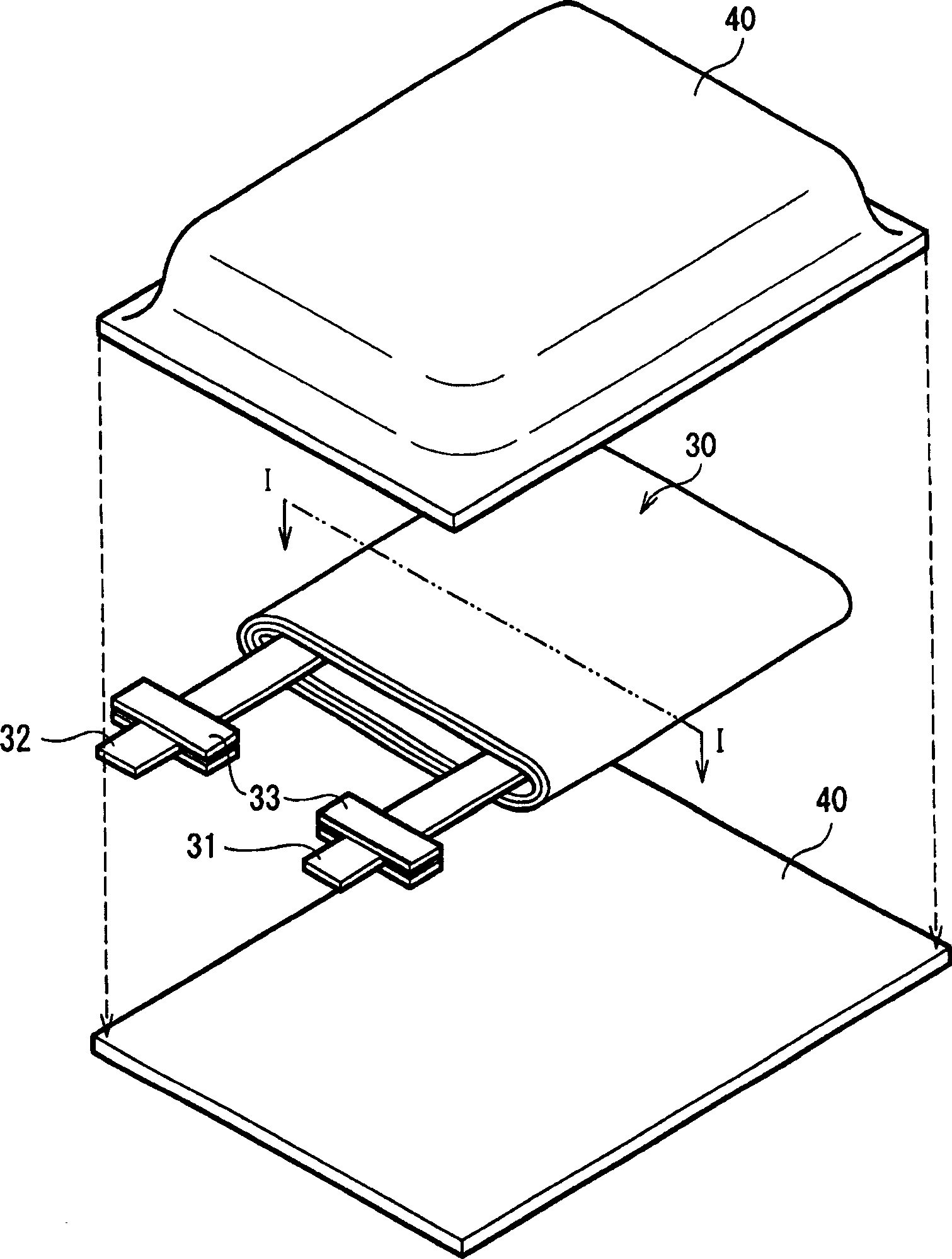
[0055] image 3 The structure of the secondary battery according to the second embodiment of the present invention is shown. This secondary battery is a so-called laminated film type secondary battery. In this secondary battery, a spirally wound electrode body 30 to which an anode lead 31 and a cathode lead 32 are attached is contained in a film packaging member 40 .
[0056] For example, the negative electrode lead 31 and the positive electrode lead 32 are respectively directed from the inside of the packaging member 40 to the outside in the same direction. The negative electrode lead 31 and the positive electrode lead 32 are respectively made of, for example, metal materials such as aluminum, copper, nickel, and stainless steel, and are respectively in the shape of a thin plate or a mesh.
[0057] The packaging element 40 is made of a rectangular aluminum laminated film in which, for example, a nylon film, an aluminum foil and a polyethylene film are bonded together in thi...
Embodiment 1
[0071] First, by using silicon as an anode active material, an anode active material layer 51B made of silicon was deposited on an anode current collector 51A made of copper foil by vacuum vapor deposition. The resultant was heat-treated in a vacuum atmosphere. In addition, the preparation of lithium cobalt composite oxide (LiCoO 2 ) as the positive electrode active material. Mix 91 parts by weight of lithium-cobalt composite oxide powder, 6 parts by weight of graphite as an electrical conductor, and 3 parts by weight of polyvinylidene fluoride as a binder, and disperse the mixture in N-methyl-2- in pyrrolidone. Next, the positive electrode current collector 52A made of aluminum foil was coated with the resultant, dried, and then compression molded by a roll press to form the positive electrode active material layer 52B and form the positive electrode 52 .
[0072] Subsequently, the formed negative electrode 51 and the formed positive electrode 52 laminated with a separator...
PUM
| Property | Measurement | Unit |
|---|---|---|
| Thickness | aaaaa | aaaaa |
Abstract
Description
Claims
Application Information
 - Generate Ideas
- Intellectual Property
- Life Sciences
- Materials
- Tech Scout
- Unparalleled Data Quality
- Higher Quality Content
- 60% Fewer Hallucinations
Browse by: Latest US Patents, China's latest patents, Technical Efficacy Thesaurus, Application Domain, Technology Topic, Popular Technical Reports.
© 2025 PatSnap. All rights reserved.Legal|Privacy policy|Modern Slavery Act Transparency Statement|Sitemap|About US| Contact US: help@patsnap.com


