
High elasticity and high strengh steel and its producing method

A technology of high-strength steel and manufacturing method, applied in the field of high-elasticity, high-strength steel and its manufacturing, can solve the problems of easy cracking, high price, enhanced self-hardening and the like

Inactive Publication Date: 2006-06-07
CF +2
View PDF5 Cites 34 Cited by
  • Summary
  • Abstract
  • Description
  • Claims
  • Application Information

AI Technical Summary

Problems solved by technology

However, the above-mentioned steels are very expensive to manufacture
[0004] In addition, South Korea and foreign countries mainly use SNCM26V (SNCM616V) as the piston of rock crusher components, which is expensive, and requires long-term carburization treatment (more than 4 days) and low-temperature treatment of low-carbon Ni-Cr-Mo steel to ensure High hardness on the outside and high toughness on the inside, chisels and drills ensure high hardness by quenching and tempering SCM440 or medium-high carbon Ni-Cr-Mo steel, making them impact-resistant and wear-resistant, but their lifespan is the same as that of The price cannot meet the requirements, and these improved steels are currently difficult to be widely used in terms of performance or manufacturing cost
[0005] In addition, in the existing wear-resistant steel, self-change occurs due to high Mn
When the Mn content exceeds 1.7% by weight, low-temperature change products are produced. Although the strength is greatly improved, the elongation is sharply reduced, and the Si / Mn ratio in low-alloy steel is small, and the pearlite / ferrite in the continuous cooling change (CCT) The start and end points of pearlite / ferrite changes are lowered, and martensite / bainite (Martensite / Bainite) changes are easy to occur. After hot working, the self-hardening property is enhanced, and cracks are easy to occur. At the same time, annealing (Annealing) is necessary for machining ) heat treatment process

Method used

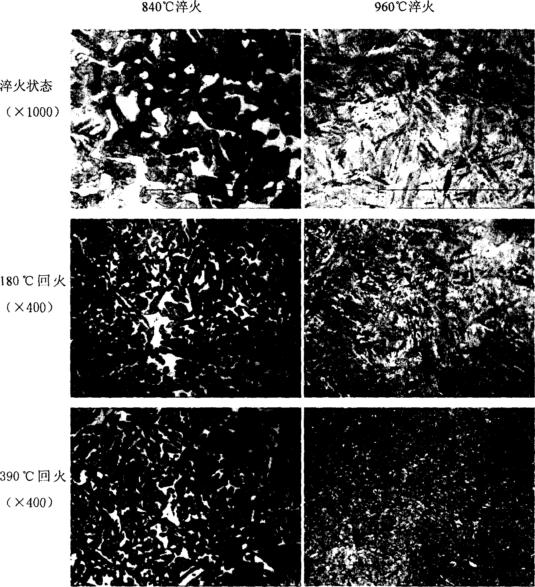
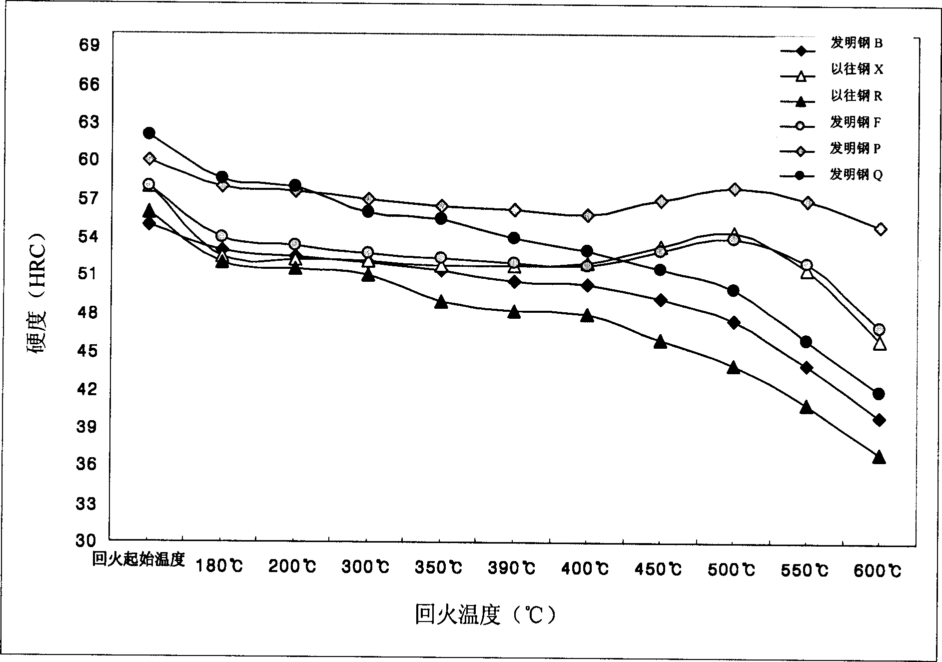
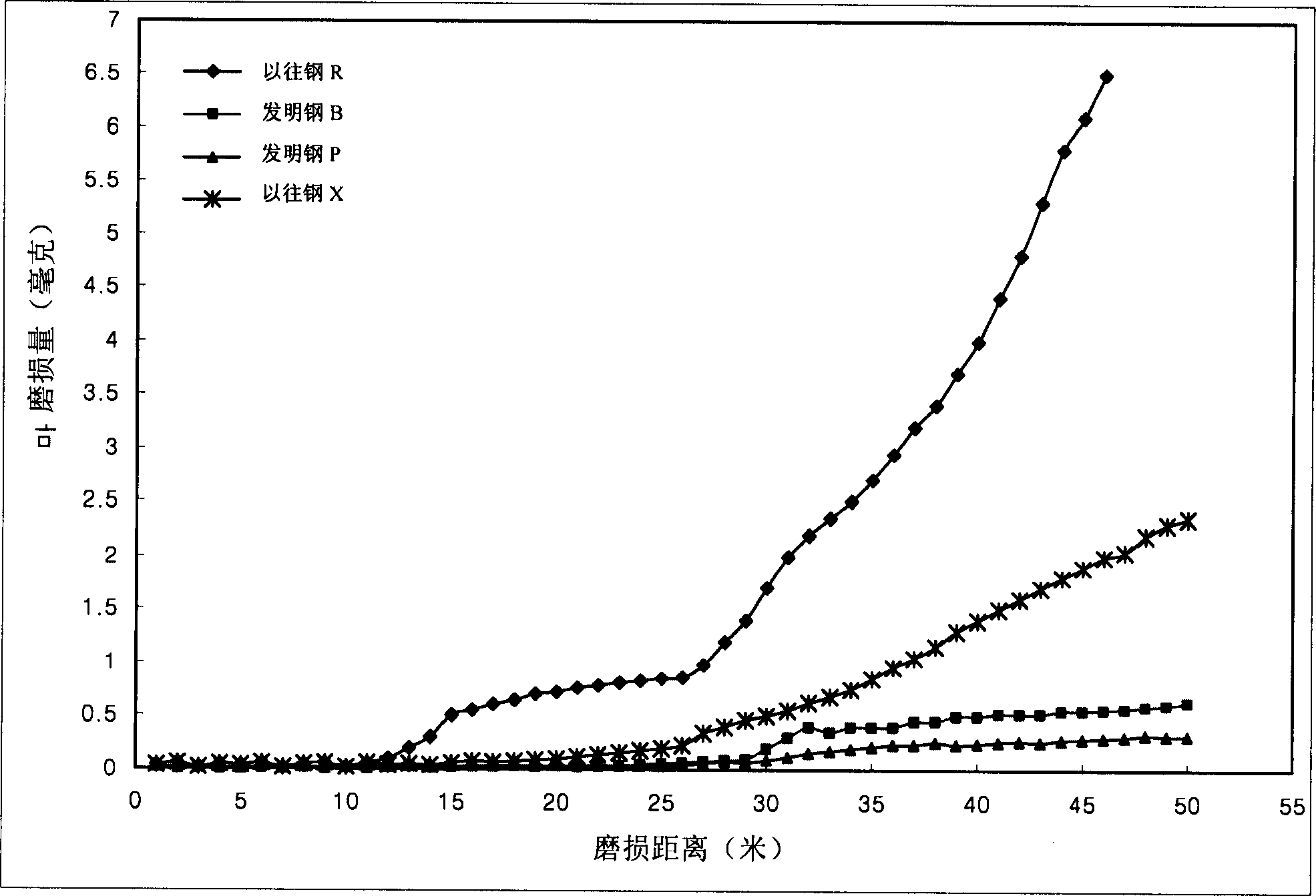

Image

  • High elasticity and high strengh steel and its producing method
  • High elasticity and high strengh steel and its producing method
  • High elasticity and high strengh steel and its producing method

Examples


Embodiment

[0074] Table 1 shows the chemical composition of the invention steel of the present invention and the conventional steel of the prior art.

[0075] Invention steels A, B, C, D, E, and F are molten steels obtained by mixing and melting pure iron and scrap iron in a 60-ton electric furnace, refining and vacuum degassing, while invention steels G, H, I, J, K, L, M, N, O, P, Q Melt pure iron and scrap iron in a 3-ton electric furnace and refine them to obtain molten steel.

[0076] Inventive steels B, C, G, L, M, and N contain: 0.26-0.36% by weight of C, 1.6-2.2% by weight of Si, 0.5-1.0% by weight of Mn, 1.4-2.4% by weight of Cr, 0.01- 0.05% by weight of Ni, 0.01-0.4% by weight of Mo, 0.005-0.04% by weight of Al, 0.05-0.1% by weight of V, 0.0025-0.02% by weight of N, 0.01-0.1% by weight of Nb, 0.0005-0.01% by weight % Ca, the remainder being Fe and unavoidable impurities.

[0077] Invention steels A and E are made of molten steel with the above components and composition ranges...


PUM


Abstract

An impact-resistant and wear-resistant high-elasticity and high-strength steel, wherein the steel contains 0.26-0.48 wt% C, 1.4-2.5 wt% Si, 0.5-1.0 wt% Mn, 1.4-2.4 wt% % Cr, 0.01-0.1% by weight of Ni, 0.01-0.5% by weight of Mo, 0.005-0.04% by weight of Al, 0.05-0.1% by weight of V, 0.0025-0.02% by weight of N, the rest is Fe and unavoidable of impurities. The impact-resistant, wear-resistant high-elasticity and high-strength steel of the present invention has high hardness, high strength, high toughness and high elasticity, and the weldability, low-temperature tempering resistance and high-temperature tempering resistance, hardenability, Mechanical properties such as wear resistance, impact toughness, and tensile strength are excellent, so when used under severe conditions, the mold life and component life are much longer than conventional steels.

Description

technical field [0001] The present invention relates to a special steel material suitable for industrial parts used under severe conditions, the material is used for industrial cutting knives, wear-resistant parts of various pulverizers, rock crushing blade parts, specifically Said, the present invention relates to be used for industrial cutting knife (knife (knife), cutter (cutter), blade (blade) etc.), various (rock, ore, wood, grain, cement etc.) permanent parts (cutting machine, liner, plate, etc.), or rock breaking blade parts - piston (piston), chisel (chisel), drill bit (drill bit), etc. are used to cut iron scrap (scrap ), stainless steel plates, copper and aluminum alloy plates and other metal and non-metallic materials with excellent performance and low manufacturing cost, high toughness, high strength and high wear resistance, and their manufacturing methods. In more detail, they relate to High-elasticity, high-strength special-purpose steel and a manufacturing met...

Claims


Application Information

Patent Timeline
IPC IPC(8): C22C38/46C22C38/50
CPCC22C38/001C22C38/005C22C38/02C22C38/06C22C38/44C22C38/46C22C38/48C22C38/52C22C38/54C22C38/58
Inventor 崔仁圭宋致福
Owner CF
Learn More