Automated testing system and method for light emitting diode

A light-emitting diode and automated testing technology, which is applied in photometry, optical performance testing, optical radiation measurement, etc., can solve the problems that the accuracy and function cannot meet people's needs, and achieve increased testing, accurate classification, and high testing accuracy Effect

Pending Publication Date: 2005-11-16
杨美英
View PDF0 Cites 29 Cited by
  • Summary
  • Abstract
  • Description
  • Claims
  • Application Information

AI Technical Summary

Problems solved by technology

[0004] Therefore, some existing test systems and test methods for light-emitting diodes cannot meet people's needs in terms of accuracy and function, and need to be improved and improved.

Method used


Image

  • Automated testing system and method for light emitting diode
  • Automated testing system and method for light emitting diode
  • Automated testing system and method for light emitting diode

Examples


Embodiment

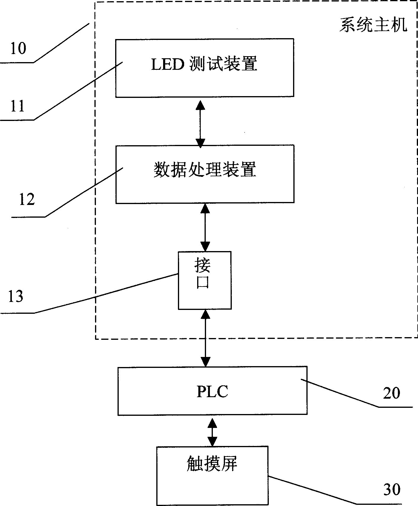
[0034] See figure 1 , a kind of automatic testing system of light-emitting diode, comprise system host 10, touch screen 30, PLC20, system host 10 comprises the LED testing device 11 of testing light-emitting diode electrical and optical parameter, the data processing of the data of tested light-emitting diode is processed The device 12 , and the interface 13 for realizing mutual communication between the data processing device 12 and the PLC20 ; and the touch screen 30 connected with the PLC20 .

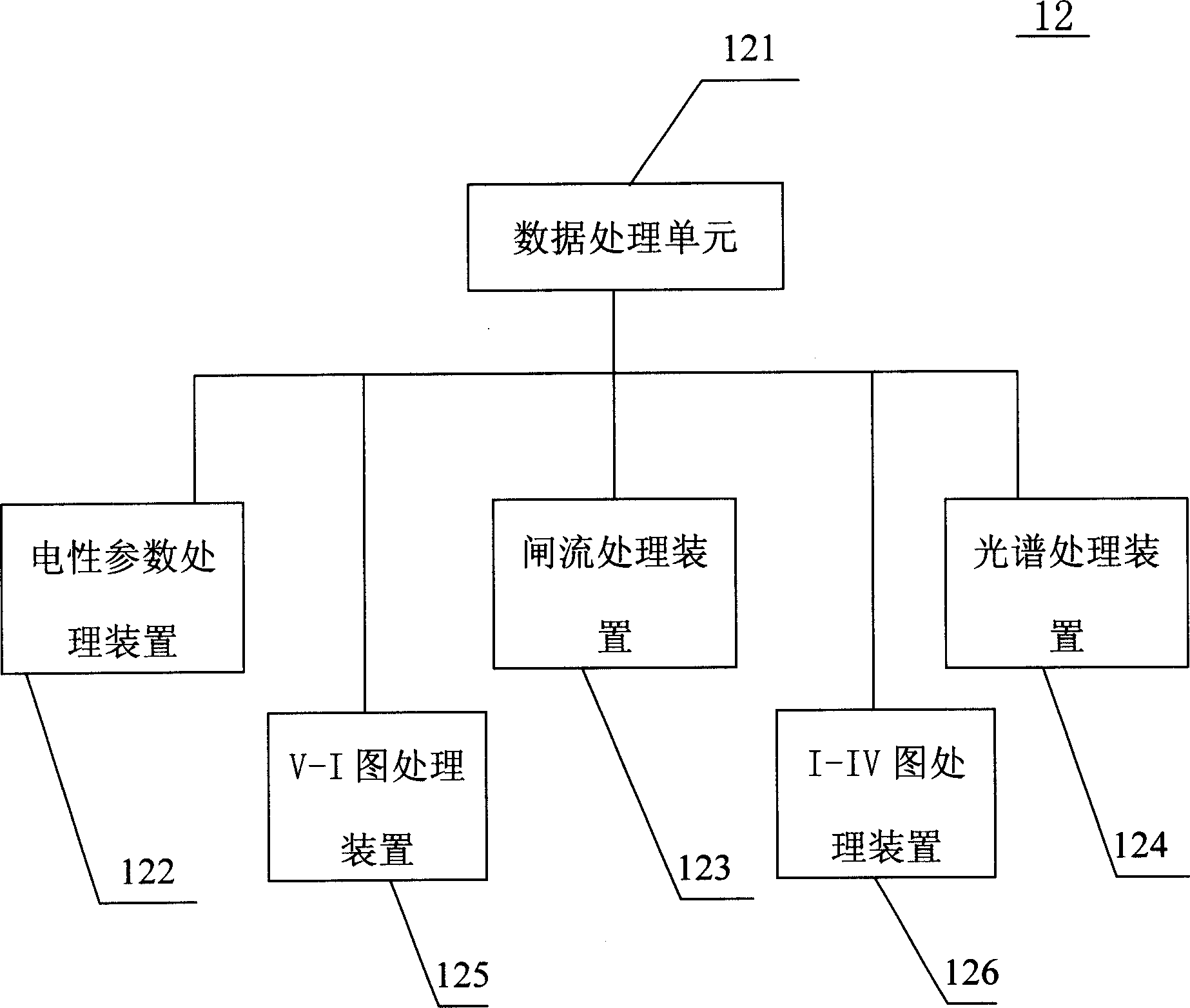
[0035] See figure 2 , the LED testing device 11 includes a data storage unit 111, an electrical parameter testing device 112 for testing the current and voltage of the LED, a thyristor testing device 113 for testing the thyristor of the LED, a spectrum testing device 114 for testing the optical parameters of the LED, and A detector 115 for testing the light intensity of the LED. See image 3 The data processing device 12 includes an electrical parameter processing device 122 for ...


PUM


Abstract

An automatic test system of LED comprises operation control desk, PLC and system host including LED test device, data processing device and communication interface. The said LED test device is featured as using parameter test device of electrical property to test LED current and voltage, using brake current device to test diode brake current and using light spectrum device to test LED optical parameters.

Description

technical field [0001] The invention relates to the field of electrical and optical testing of light-emitting diodes, in particular to an automatic testing system and method for light-emitting diodes. Background technique [0002] After the LED is packaged, its electrical or optical parameters must be tested to ensure its yield or applicability, and the testing method must use a dedicated LED testing instrument for detection. In recent years, there have been light-emitting diode testing instruments with a high degree of automation and reliable testing accuracy. [0003] There are some types of light-emitting diode test systems currently on the market. Compared with the previous artificial spectroscopic, they have many advantages, such as fast speed, higher spectroscopic accuracy than manual, and higher accuracy of electrical parameters. However, there are also some defects, such as the forward voltage, because the applied current is instantaneous during the test, and the fo...

Claims


Application Information

Patent Timeline
Patent Type & Authority Applications(China)
IPC IPC(8): G01R31/26
Inventor 韩金龙罗会才杨少辰
Owner 杨美英
Why Eureka
Try Eureka