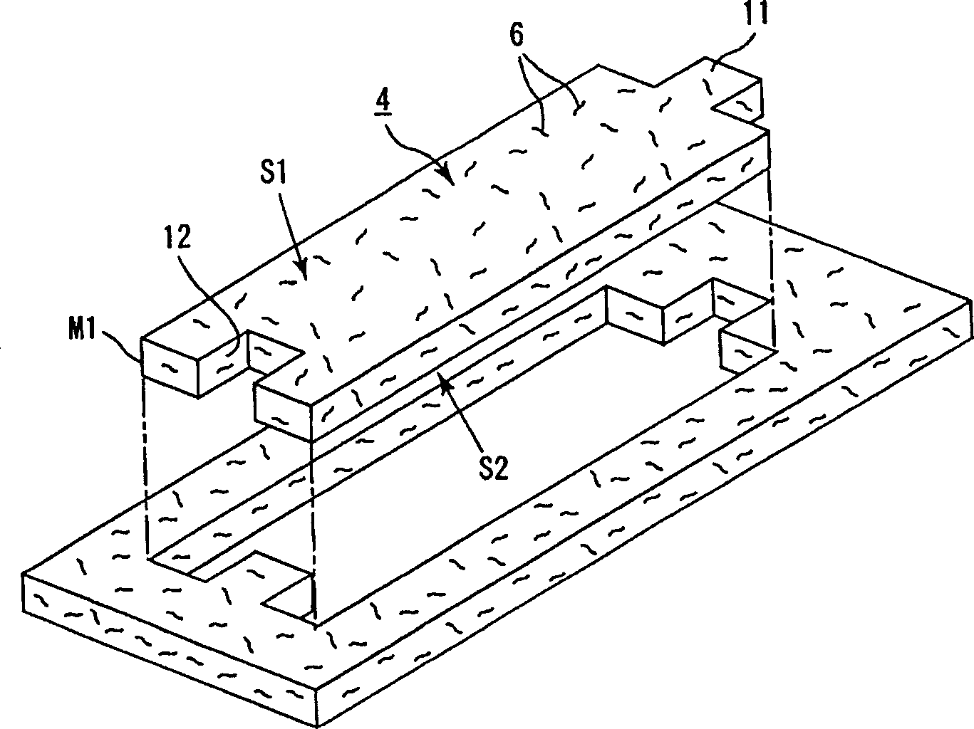
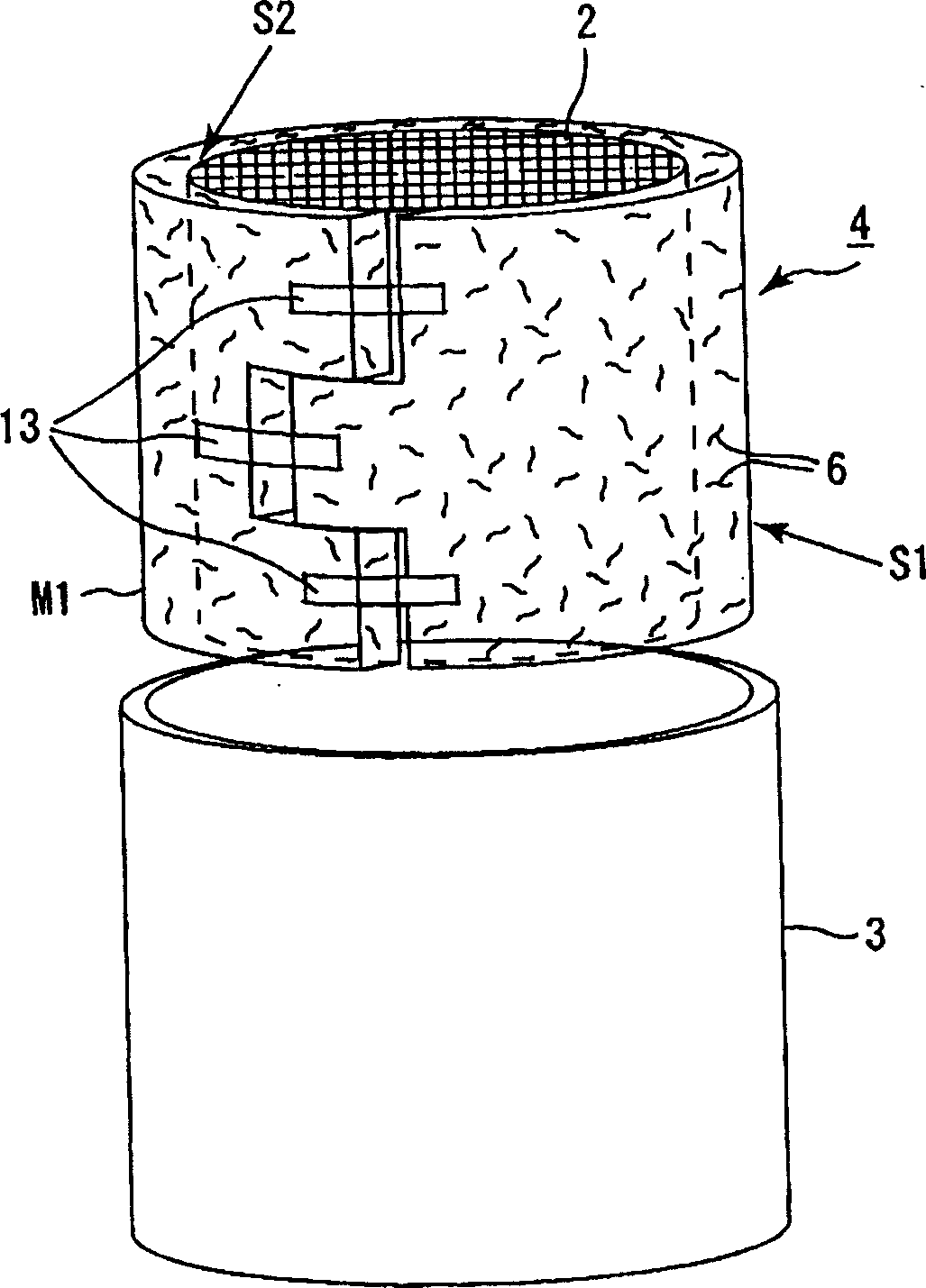
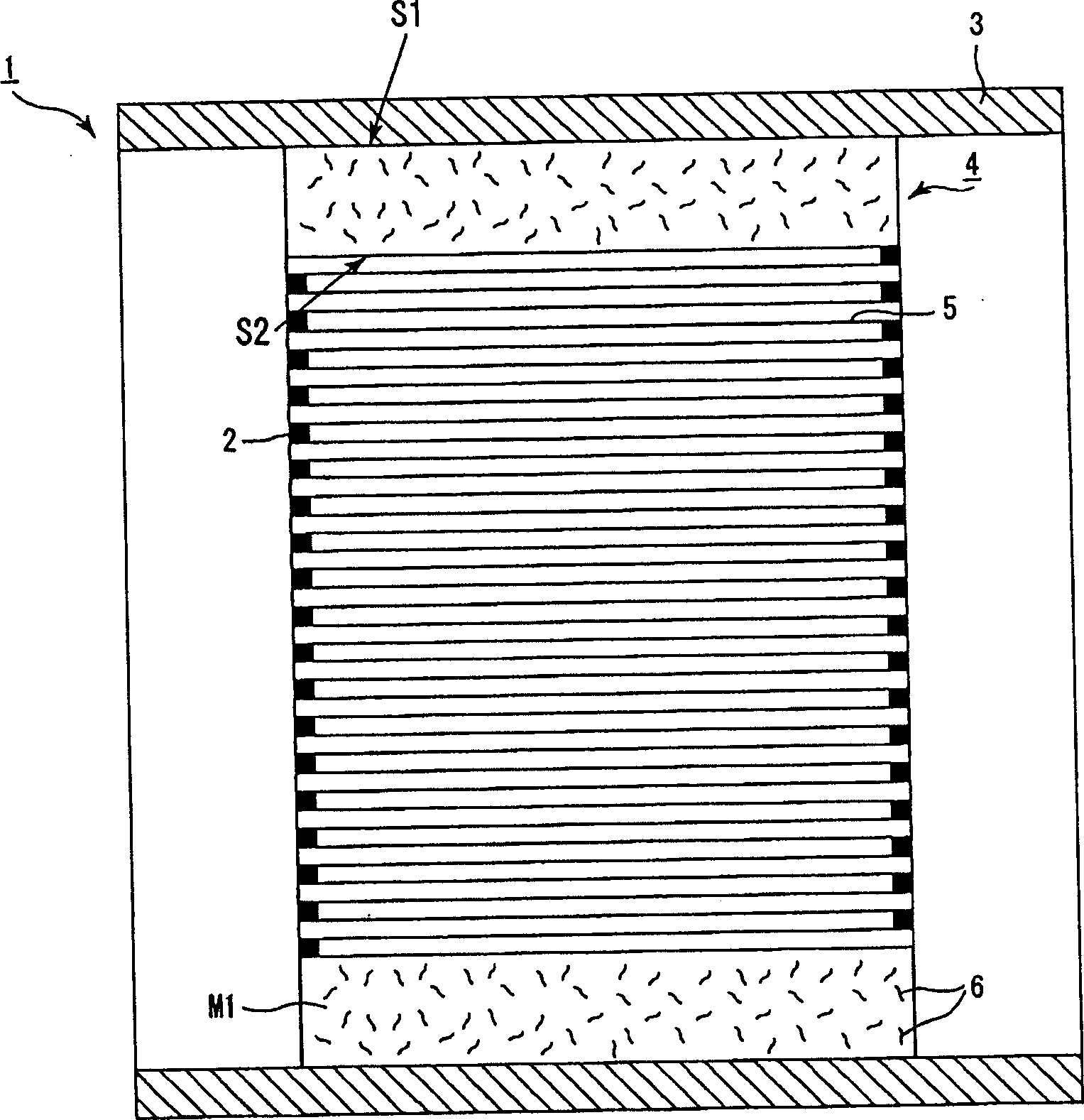
Catalytic cracking device
A technology of catalytic conversion and catalyst carrier, which is used in exhaust devices, mufflers, catalyst protection, etc., can solve the problem of not being able to obtain quality stability and tightening sealing materials.
- Summary
- Abstract
- Description
- Claims
- Application Information
AI Technical Summary
Problems solved by technology
Method used
Image
Examples
preparation example Construction
[0273] According to the preparation method of the first group of embodiments of the present invention, the precursor fiber is heated in an environment where it is difficult to oxidize the carbon component contained in the precursor fiber, thereby performing the calcination step of sintering the precursor fiber. Therefore, this allows a large amount of carbon components to remain in the aluminum silicon fiber 6, thus ensuring that the aluminum silicon fiber 6 having excellent mechanical strength can be easily obtained.
[0274] According to the preparation method of the first group of embodiments of the present invention, the environment in which the calcination step is performed uses an inexpensive nitrogen atmosphere. Therefore, this can reduce the production cost of the fastening seal material 4. In addition, since the heating step is performed within the preferred calcination temperature range, this can stably obtain high-strength aluminum-silicon fibers 6.
[0275] According t...
Embodiment 1
[0534] In Example 1, first, an alkaline aqueous solution of aluminum chloride (23.5 wt%), silica sol (20 wt%, the particle size of silica is 15 nm) and polyvinyl alcohol (10 wt%) were mixed to A spinning stock solution is prepared, and the polyvinyl alcohol is a drawing performance imparting agent. Then, the resultant spinning stock solution was concentrated using an evaporator under a vacuum of 50°C to obtain a spinning stock solution having a concentration of 38% by weight and a viscosity of 1500 poise.
[0535] After the spinning stock solution is prepared, the spinning stock solution is continuously discharged into the air through the nozzle (the cross section is a perfect circle) of the spinning equipment, and the obtained precursor fiber is wound up while drawing.
[0536] Secondly, the precursor fiber is heated (pretreatment), heated in an electric furnace at 250°C, atmospheric pressure and nitrogen atmosphere for 30 minutes, and then in the same way, heated in an electric ...
Embodiment 2 and 3
[0545] In Examples 2 and 3, aluminum-silicon fibers 6 were prepared in substantially the same order as in Example 1, except that the temperature and time of calcination were changed according to Table 1. As a result, aluminosilicate fibers 6 excellent in mechanical strength can be obtained.
[0546] In addition, when forming samples for the surface pressure test, the initial surface pressure, the surface pressure after the durability test, and the ratio of the surface pressure decrease over time were tested on these samples, and the results were optimized in the same manner as in Example 1. The results (see Table 1).
[0547] Of course, no changes in color and residual carbon content were observed.
[0548] In addition, the fastening sealing material 4 is prepared to obtain a catalytic converter 1, and the catalytic converter 1 is equipped with a continuous driving experiment. As a result, during driving, no noise was generated, and the catalyst carrier 2 did not turn black. There...
PUM
| Property | Measurement | Unit |
|---|---|---|
| tensile strength | aaaaa | aaaaa |
| bending strength | aaaaa | aaaaa |
| diameter | aaaaa | aaaaa |
Abstract
Description
Claims
Application Information
 - R&D Engineer
- R&D Manager
- IP Professional
- Industry Leading Data Capabilities
- Powerful AI technology
- Patent DNA Extraction
Browse by: Latest US Patents, China's latest patents, Technical Efficacy Thesaurus, Application Domain, Technology Topic, Popular Technical Reports.
© 2024 PatSnap. All rights reserved.Legal|Privacy policy|Modern Slavery Act Transparency Statement|Sitemap|About US| Contact US: help@patsnap.com


