
Magnesium alloy low-pressure casting method

A low-pressure casting and low-pressure casting machine technology, applied in the field of low-pressure casting of magnesium alloys, to achieve the effects of reducing production costs, reducing environmental pollution, and improving quality

Inactive Publication Date: 2005-09-07
SHENYANG RES INST OF FOUNDRY
View PDF0 Cites 7 Cited by
  • Summary
  • Abstract
  • Description
  • Claims
  • Application Information

AI Technical Summary

Problems solved by technology

Electromagnetic pump filling requires that the magnesium liquid level in the holding furnace supplying magnesium liquid maintain a certain liquid level, so it is only suitable for small pieces

Method used


Image

  • Magnesium alloy low-pressure casting method
  • Magnesium alloy low-pressure casting method
  • Magnesium alloy low-pressure casting method

Examples


Embodiment 1

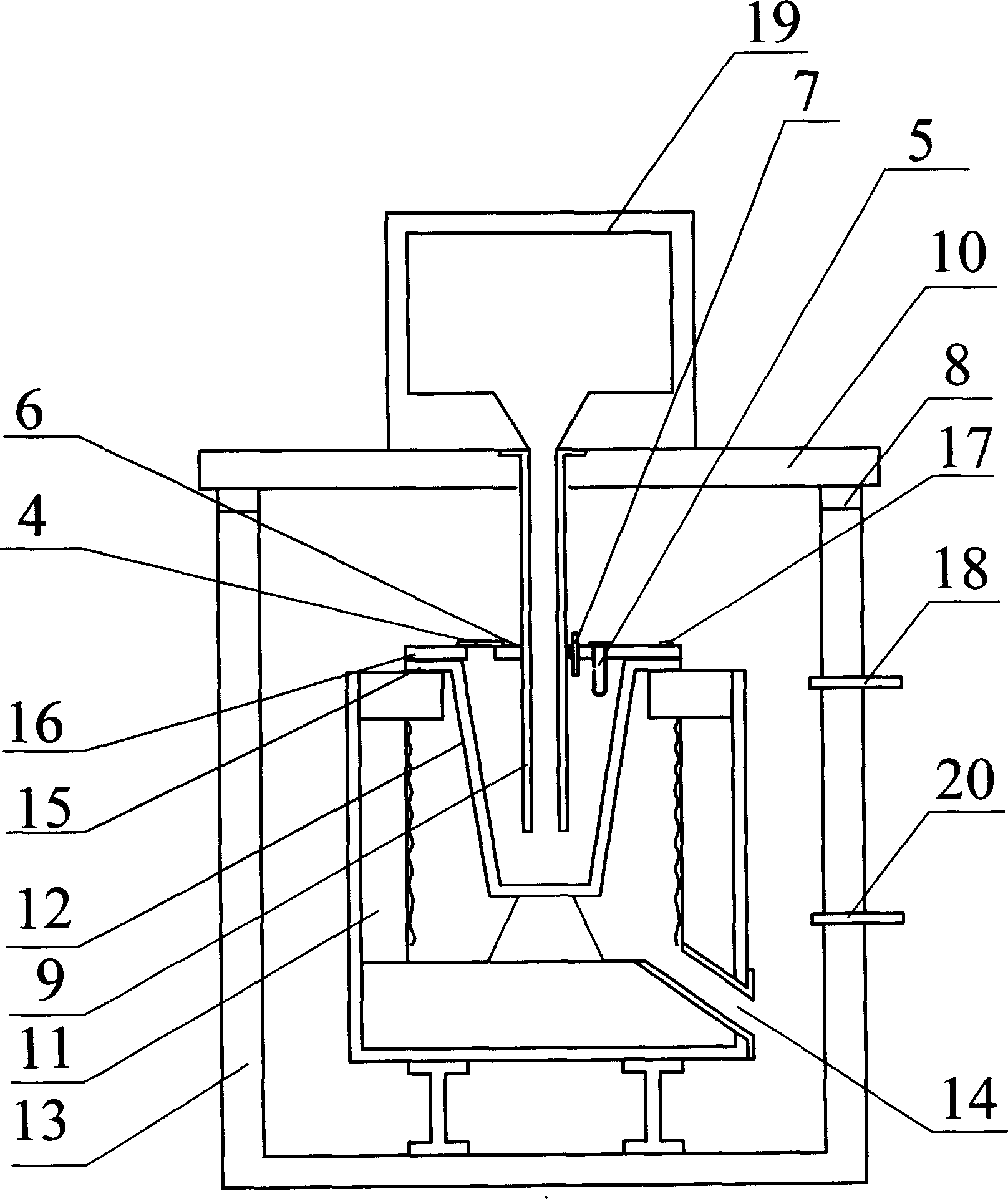
[0046] The host of the magnesium alloy low-pressure casting machine includes a holding furnace 11 , a crucible 12 , a sealing cover 10 , a pressure tank 13 , a riser pipe 9 and a casting mold 19 . Holding furnace 11 is installed in pressure tank 13, and is supported by I-shaped support. A vent 14 is arranged on the side wall of the holding furnace 11. The crucible 12 is installed in the holding furnace 11 , and the upper edge 15 of the crucible 12 overlaps with the upper port of the holding furnace 11 .

[0047] When the magnesium alloy liquid in the crucible has been refined and the temperature is adjusted to the casting temperature, start to place protective gas generating substances, namely protective agents 1, 2 and 3. Protective agent 1 is composed of 100g of sulfur powder and 200g of boric acid mixed uniformly. The protective agent 1 is loaded into a container 5 with an inner cavity with a height-to-diameter ratio of 2. The container 5 is a double-layer cylinder made ...

Embodiment 2

[0050] The second embodiment is basically the same as the first embodiment, except that the protective agent 1 is made by mixing 70g of sulfur powder and 250g of boric acid. Protectant 2 consists of 100g pyrite powder and 100g dry charcoal powder. Protective agent 3 is made up of 100g sulfur powder and 300g boric acid, and covers 20mm thick 100-200 mesh quartz sand in the container that holds protective agent 3. Two containers for containing protective agent 3 are arranged on both sides of the rising liquid pipe hole 6 of the crucible cover, apart from the 230mm place of the rising liquid pipe hole.

Embodiment 3

[0052] Embodiment 3 is basically the same as Embodiment 1, except that the protective agent 1 is made by mixing 120g of sulfur powder, 100g of boric acid and 200g of 70-140 mesh magnesia. Protective agent 2 is composed of 50g of sulfur powder, 100g of coke powder and 150g of pyrite powder. First, 100g of coke powder is evenly sprinkled on the sulfur powder, and then 150g of pyrite powder is evenly sprinkled on the top. Protective agent 3 is composed of 160g of yellow Composed of iron ore powder and 80g 70-140 mesh quartz sand, two containers containing protective agent 3 are respectively placed on both sides of the observation hole on the crucible cover 5 and the center line of the riser hole, 200mm away from the riser hole.


PUM


Abstract

The invention is the magnesium alloy low-pressure casting method, which is to put the protective gas creator on the cover of the crucible or in the crucible that is in the pressure tank of the casting machine. The protective gas creator comprises: the protective agent 1, 2 and 3; the protective 1 is composed of sulfur powder and boric acid powder or of the mixing of sulfur powder, boric acid and magnesium sands; the protective agent 2 comprises sulfur powder or pyrite and carbon powder; the protective agent 3 is sulfur powder or pyrite, or the mixture of sulfur powder, pyrite and boric acid. The side wall of the container filled with the protective agent 1 has gas outlet and in the crucible; the protective agents 1 and 2 are in the open containers and on the crucible cover. The invention ensures the safe operation of the low-pressure casting, improves the quality of magnesium alloy cast, lowers the cost and reduces the environmental pollution.

Description

(1) Technical field [0001] The invention relates to a casting technology, in particular to a magnesium alloy low-pressure casting technology. (2) Background technology [0002] In today's world, the requirements for environmental protection and energy saving are getting higher and higher. As the lightest, highest specific strength and easy-to-recycle engineering structural material, magnesium alloy has been more and more widely used in light industrial products such as automobiles, electronics, electrical engineering, sports, leisure products and daily consumer goods in recent years. The weight of the car is reduced by 10%, and the fuel consumption is reduced by 6-8%. Reducing the quality means reducing fuel consumption and reducing pollutant emissions. Automobile lightweight has become the main development trend of domestic and foreign automobile industry. As the engineering material with the highest specific strength, magnesium alloy has become the most eye-catching gree...

Claims


Application Information

Patent Timeline
Patent Type & Authority Applications(China)
IPC IPC(8): B22D21/04
Inventor 冯志毅李立善申泽骥冯志军
Owner SHENYANG RES INST OF FOUNDRY
Learn More