Optical waveguide article including a fluorine-containing zone

A product and optical technology, applied in the field of waveguide, can solve problems such as amplification and harmful power conversion efficiency, and achieve the effects of low loss, low background attenuation, and wide gain spectrum

Inactive Publication Date: 2005-06-15
3M INNOVATIVE PROPERTIES CO
View PDF0 Cites 7 Cited by
  • Summary
  • Abstract
  • Description
  • Claims
  • Application Information

AI Technical Summary

Problems solved by technology

[0013] At the same time, it is also recognized that the presence of a large amount of fluorine in oxyfluoride glass is good for preventing phase separation and integration of rare earth elements, while at the same time, such as Er 3+ Groups of fluorescent rare earth ions have detrimental effects on optical amplifier spectral width, excited state lifetime, amplification threshold (pump power required to flip optical amplifier), and optical amplifier power conversion efficiency

Method used


Image

  • Optical waveguide article including a fluorine-containing zone
  • Optical waveguide article including a fluorine-containing zone
  • Optical waveguide article including a fluorine-containing zone

Examples


example 2

[0081] Example 2 - Fluorine Reservoir

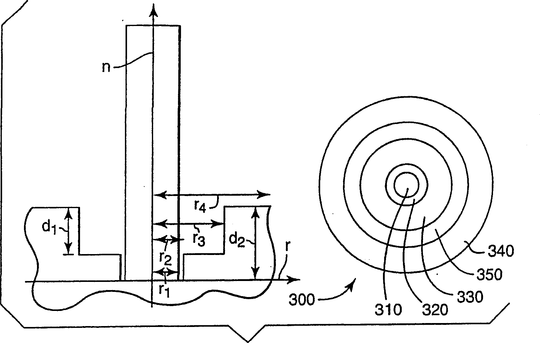
[0082] have something like image 3 The shown distribution of DCLR preforms was fabricated by MCVD techniques. use SiF 4 (30sccm), POCl 3 (100sccm) and SiCl 4 (950sccm) five deposition passes were made to prepare the inner cladding, and SiF 4 (flow rate is 350sccm), POCl 3 (100sccm), and SiCl 4 (350 sccm) A sixth deposition pass was made to give a fluorosilicate reservoir region with -4 mol% fluorine. Its core is lanthanum aluminum silicate doped with erbium. The flattened preform is drawn and segmented, elongated, and overflattened. Fiber was drawn and characterized in the same manner as in Example 1. Wavelength dispersive X-ray analysis of a very small amount of preform gave a fiber with >0.5 mol% (>0.15 wt%) fluorine in the fiber, with ~4 mol% fluorine rings and an inner cladding with ~2.1 mol% fluorine.

[0083] optical fiber

type

f core (in a very small amount

preform core

Fluorine in

f rin...

example 3

[0086] Example 3 - L-band fiber with and without fluorine reservoir

[0087] Fibers suitable for L-band were fabricated as in Examples 1 and 2. Both fibers have nominal dopant and modifier cation concentrations. Data on preforms and optical fibers are shown below:

[0088] optical fiber

example 4

[0089] EXAMPLE 4 - COMPARISON OF THE EFFECT OF DIRECT DOPING HEAT TREATMENT TO FLUORINE RESERVOIR DESIGNED FIBERS

[0090] The present invention also provides a method for adjusting the distribution of fluorine in the radial direction. The radial distribution of the coefficient of thermal expansion (CTE) and viscosity through the diffusion of fluorine from the outer region of the core to the core is provided in the present invention.

[0091] The diffusion equation can be solved for the case of diffusion from a distributed source in cylindrical coordinates. The radial coordinate is r, the time is t, and the concentration distribution is C(r, Dt). The initial concentration Co is distributed on the vector r 1 and r 2 on the casing. The diffusion coefficient D is assumed to be independent of concentration. The derivation of this equation can be found in Carslaw and Jaeger, Heat Conduction in Solids (1948).

[0092] C ( r ...


PUM


Abstract

An optical article including a core; at least one cladding layer; and a narrow fluorine reservoir between the core and the cladding layer. The fluorine reservoir has a higher concentration of fluorine than either the cladding layer or the core. One particular embodiment includes a core including a halide-doped silicate glass that comprises approximately the following in cation-plus-halide mole percent 0.25-5 mol % Al2O3, 0.05-1.5 mol % La2O3, 0.0005-0.75 mol % Er2O3, 0.5-6 mol % F, 0-1 mol % Cl.

Description

Background of the invention [0001] The present invention relates to waveguides with novel optical designs and to their fabrication. In particular, the present invention relates to a novel optical fiber and preform comprising a ring having a high fluorine concentration and a method of manufacturing the same, and to the composition of the core glass. [0002] The term optical waveguide product is meant to include optical preforms (at any stage of production), optical fibers and other optical waveguides. Typically, optical fibers are made by first forming a glass preform. There are several methods of making preforms, including modified chemical vapor deposition (MCVD), outside vapor deposition (OVD), and vapor axial deposition (VAD). The glass preform consists of a tube of silica. In MCVD, thin layers of various materials are deposited inside the tube; in OVD and VAD, various thin layers are deposited on the outside of the mandrel. Typically, the structure is then strengthene...

Claims


Application Information

Patent Timeline
Patent Type & Authority Applications(China)
IPC IPC(8): C03B37/018C03C3/06C03C13/04C03C23/00C03C25/10C03C25/60G02B6/00G02B6/036G02B6/255H01S3/067
CPCC03B37/01807C03B2201/12C03B2201/28C03B2201/36C03B2203/22C03C3/06C03C13/046C03C23/0095C03C25/104C03C25/1065C03C25/608C03C2201/11C03C2201/12C03C2201/3417C03C2201/3476C03C2201/36C03C2203/52G02B6/02009G02B6/02285G02B6/03627G02B6/03633G02B6/0365G02B6/03655G02B6/03694G02B6/2551H01S3/06708H01S3/06716H01S3/06729H01S3/06754
Inventor M·T·安德森C·R·沙德特J·R·昂斯托特L·J·唐纳尔兹A·O·沙瑞利
Owner 3M INNOVATIVE PROPERTIES CO
Why Eureka
Try Eureka