Double metal combining method in sand mould
A metal composite, dual-material technology, applied in the production of metal castings, can solve the problems of troublesome operation, slow heat transfer of sand mold, oxidation of coated parts, etc., to improve heating efficiency, shorten heating time, and ensure the effect of heating temperature
- Summary
- Abstract
- Description
- Claims
- Application Information
AI Technical Summary
Problems solved by technology
Method used
Image
Examples
Embodiment 1
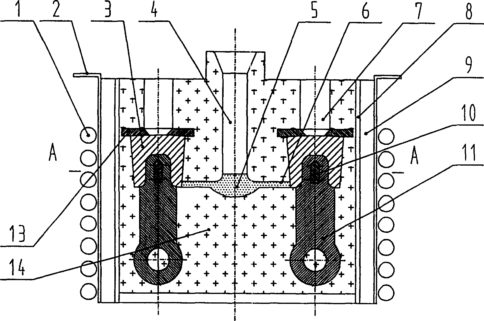
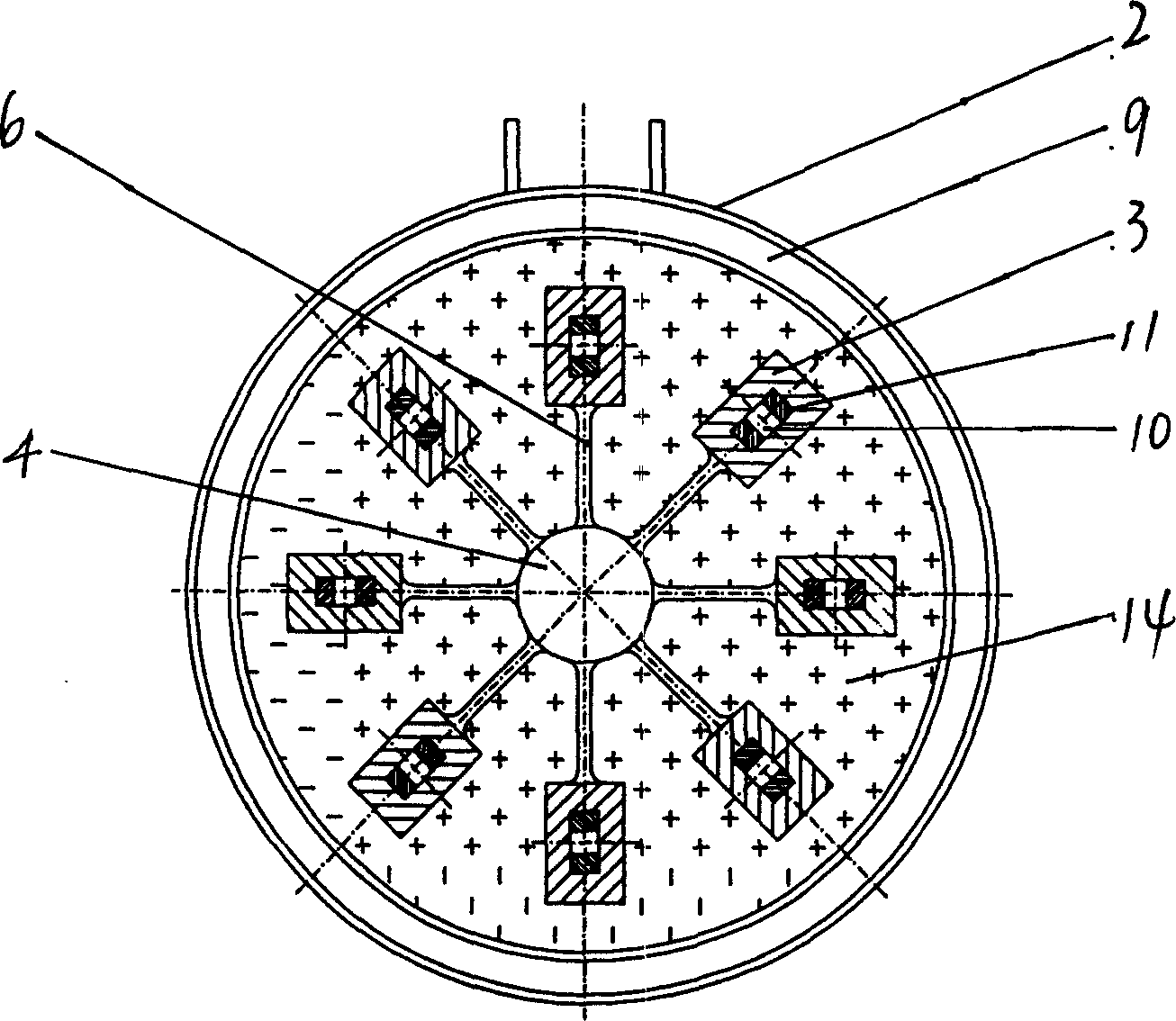
[0025] Such as figure 1 , figure 2 As shown, the meanings of the labels in the figure are as follows: 1. Heating induction coil; 2. Protective sleeve; 3. The end of the hammer head to be compounded; 4. Sprue; , feeding riser; 8, sand mold jacket; 9, the gap between the sand box and the protective sleeve; 10, the mechanical combination hole between the hammer end and the hammer handle; 11, the hammer handle; 13, the easy-cut riser piece ; 14, sand mold.
[0026] The workpiece production process is as follows:
[0027] The formed solid carbon steel metal hammer handle 11 is prefabricated according to requirements, and a hole 10 is processed at the joint part of the hammer handle 11 and the high chromium cast iron hammer head end 3 to be compounded, and the hammer handle 11 is prepared for compounding. Purification treatment, grinding with grinding wheels to remove scale and other impurities that hinder metallurgical bonding. Then apply a layer of anti-oxidation protection a...
Embodiment 2
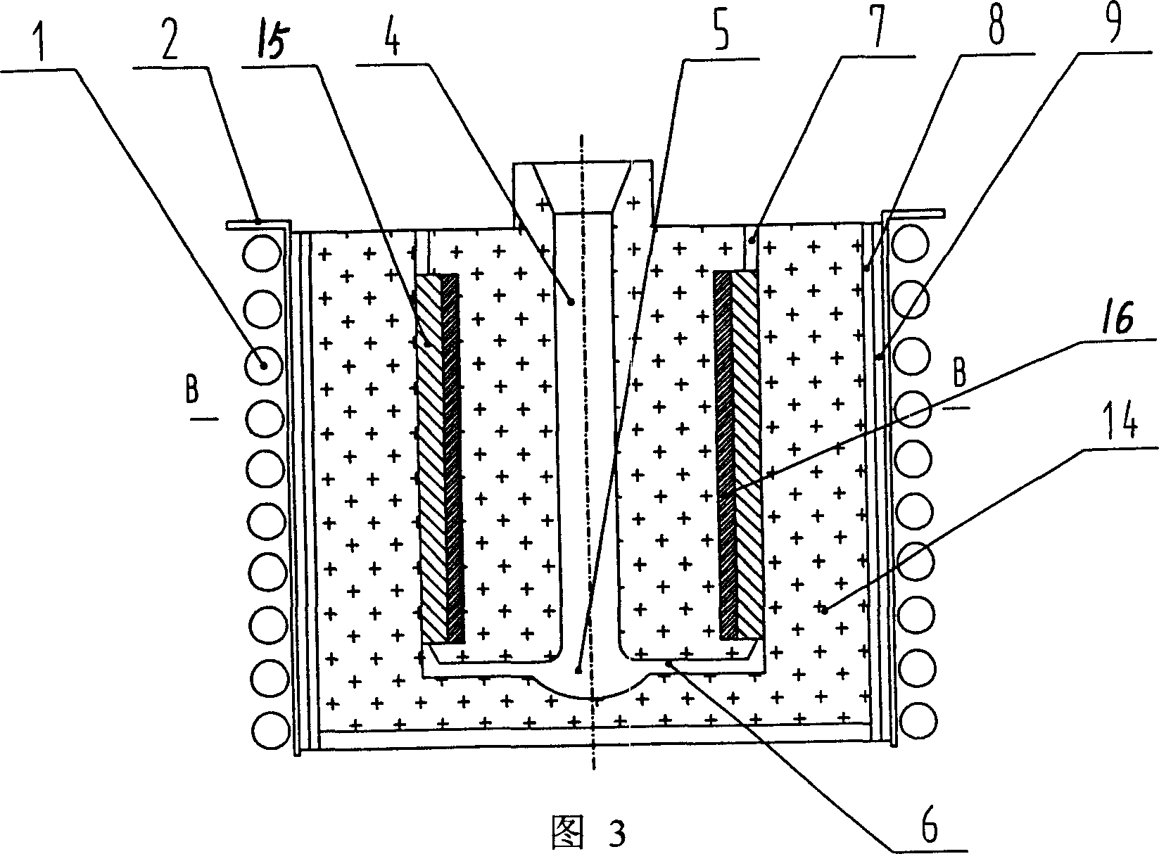
[0035] As shown in Figure 3, Figure 4 , Figure 5 , Figure 6 As shown, the meanings of the labels in the figure are as follows: 1. Heating induction coil; 2. Protective sleeve; 15. The cavity of the outer layer part to be compounded; 3. The cavity of the outer layer part to be compounded; 4. The sprue; 5. Gate socket; 6. Inner runner; 7. Feeding outlet riser; 8. Sand mold coat; 9. The gap between the sand box and the protective sleeve; 16. The solid matrix layer lining the wheel-shaped parts; 14- 2. Sand mold; 14-1. Sand core.
[0036] The production process of this part is as follows:
[0037]The solid matrix layer 16 lined with carbon steel is pre-produced, and then the compound surface of the formed solid metal to be compounded is pre-purified and polished, and a layer of anti-oxidation protection agent is adhered thereon.
[0038] The sand-making core 14-1 is used to create the sprue 4 and the inner runner 6 of the pouring system, and at the same time, put the inner ...
Embodiment 3
[0043] Such as Figure 7 , Figure 8 As shown, the meanings of the labels in the figure are as follows: 1. Heating induction coil; 2. Protective sleeve; 3'. Foam plastic model; 4. Sprue; Air outlet riser; 8, sand mold coat; 9, gap between sand box and protective cover; 11', insert block; 12, nail; 14, sand mold.
[0044] In this process, the workpiece to be compounded is made into a cemented carbide insert 11' in advance, with nails 12 on the insert 11', and the insert 11' is connected with the foam plastic model 3' in advance to form the workpiece shape as a model. When molding, it is put into the sand mold 14, and the whole model forms a cavity together with the insert 11' after the molding, and the foam plastic 3' vaporizes after preheating to form a base metal cavity, while the nail 12 on the insert 11' is Fix the insert 11' at the corresponding position in the cavity. After pouring, the high manganese steel matrix metal liquid vaporizes the remaining foam and fills the ...
PUM
 Abstract
Description
Claims
Application Information
 - R&D
- Intellectual Property
- Life Sciences
- Materials
- Tech Scout
- Unparalleled Data Quality
- Higher Quality Content
- 60% Fewer Hallucinations
Browse by: Latest US Patents, China's latest patents, Technical Efficacy Thesaurus, Application Domain, Technology Topic, Popular Technical Reports.
© 2025 PatSnap. All rights reserved.Legal|Privacy policy|Modern Slavery Act Transparency Statement|Sitemap|About US| Contact US: help@patsnap.com


