
Three-phase split phase-shifting transformer for high-voltage frequency conversion and its use

A phase-shifting transformer and high-voltage frequency conversion technology, which is applied in the direction of transformers, transformers/inductor coils/windings/connections, inductors, etc., can solve the problems of grid harmonic pollution, low power factor and efficiency, and low output frequency. Solve harmonic pollution, reduce harmonic loss, and reduce the effect of grid-side current harmonics

Inactive Publication Date: 2004-09-15
谭勇
View PDF0 Cites 22 Cited by
  • Summary
  • Abstract
  • Description
  • Claims
  • Application Information

AI Technical Summary

Problems solved by technology

From the first generation of SCR to the second generation of GTO, although the voltage level and power size can meet their requirements, the modulation frequency is low, the harmonic content is high, the power factor and efficiency are low, and the structure is complex, and the performance is not satisfactory. It was not developed until the emergence of the third generation IGBT (insulated gate bipolar transistor) and the fourth generation IGCT (integrated gate-controlled converter transistor).
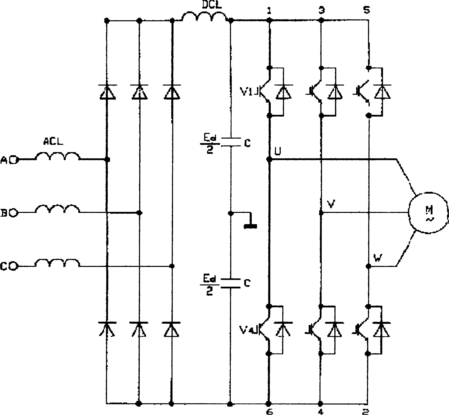
Second, until the end of the 1990s, high-voltage inverters did not have a basically consistent main circuit topology like low-voltage general-purpose inverters (attached figure 1 )
[0005] The disadvantages of AC-AC are: low output frequency (less than 1 / 2 grid frequency), low grid power factor, affected by side frequency harmonics, reactive power compensation and filtering devices are required, high cost, and large area occupation
The harmonic pollution of the high-voltage frequency converter to the power grid and the impact on the motor are relatively serious

Method used


Image

  • Three-phase split phase-shifting transformer for high-voltage frequency conversion and its use
  • Three-phase split phase-shifting transformer for high-voltage frequency conversion and its use
  • Three-phase split phase-shifting transformer for high-voltage frequency conversion and its use

Examples


Embodiment Construction

[0064] Below in conjunction with accompanying drawing and specific example for further detailed description:

[0065] Figure 9 That is, N power units connected in series using the transformer of the present invention are multi-level PWM frequency converters. Its power unit is a common, mature, reliable, low-voltage single-phase PWM inverter. Relying on an integrated, specially designed multi-winding transformer T with independent valve sides and a certain phase shift, if this low-voltage inverter is reorganized—the units are multiplexed and stacked in series, 3N identical Low-voltage single-phase inverters have been successfully applied to high-voltage and high-power inverters. It ideally solves the problem of harmonic interference which is difficult to avoid with general 6 or 12 pulses.

[0066] attached Figure 10 One of the power units, the AC-DC-AC voltage source PWM inverter with single-phase output, is drawn. Diodes form a three-phase bridge rectifier circuit, powe...


PUM


Abstract

In the transformer, line side windings connected in star type continuous form is adopted in inner side. Structure of outer side is three groups divided, N groups phase shifted cake typed line side windings. The invented transformer solves issues of harmonic polluting on power grid and harmonic wastage, possessing advantages: reliable operation, simple maintenance, small harmonic current at power grid side, low noise, low heat generated, high power factor. When being applied to high voltage frequency control, the invention solves issues: heating of motor, torque ripple, influence of dv / dr and common mode voltage on insulation of motor. The invention can reaches ideal effect of harmonic elimination even if out of balanced currents occurred, providing advantages of approximate to sinusoidal waveform output, high conversion efficiency etc.

Description

technical field [0001] The invention relates to a transformer and high-voltage frequency conversion technology, in particular to a three-phase split phase-shifting transformer for high-voltage frequency conversion and its application. Background technique [0002] At present, the energy-saving potential of frequency conversion speed regulation of high-voltage AC motors is considerable: although 50Hz is the best frequency for power generation, it is not the best frequency for all electrical equipment. Most of the on-grid AC motors, which account for 2 / 3 of the country's total power consumption, work under the conditions of full voltage, rated frequency, and constant speed, with an efficiency of only 60% and a power factor of only 0.7. If it can work at 5-45Hz, its power saving rate is 20-60%. In the total capacity of AC motors in the network, the capacity of small and medium-sized low-voltage motors accounts for 40%, and the capacity of large-capacity motors in high-voltage ...

Claims


Application Information

Patent Timeline
IPC IPC(8): H01F27/28H01F38/00H02M5/44H02M5/458
Inventor 谭勇
Owner 谭勇
Learn More