
Foot warming heating element and method of manufacturing foot warming heating element

A heat-generating body and foot technology, applied in the direction of heating element shape, heat exchange material, ohmic resistance heating, etc., can solve the problems of production equipment operating time, operator working time limitation, poor flow value, and productivity decline.

Inactive Publication Date: 2004-08-04
MYCOAL
View PDF10 Cites 11 Cited by
  • Summary
  • Abstract
  • Description
  • Claims
  • Application Information

AI Technical Summary

Problems solved by technology

As a result, after mixing the heat-generating components but before filling the produced heat-generating body in the outer package, a heat-generating reaction occurs, and the water vapor pressure of the heat-generating components rises, causing the heat-generating body to expand, thereby causing problems It is difficult to pack the heat-generating body into an airtight packaging bag due to expansion
[0022] Moreover, in common heat-generating components, a heat-generating reaction occurs after mixing the heat-generating components but before filling the produced heat-generating body in an outer package, resulting in occurrence of The loss caused, moreover, the reaction product of the heat-generating reaction is solidified, resulting in various problems, such as reduced output, difficult handling, complicated maintenance of production equipment, restrictions on the operating time of production equipment and the working time of operators, processing of solidified substances Difficulty, etc.
[0023] In the method of intermittently moving the base material and dripping the heat-generating component while the base material is paused, there is a problem in that productivity decreases due to frequent repetition of the pause and start of the base material
[0024] In the method of dropping the heat-generating material while moving the base material at a constant speed while moving the drip net at the same speed as the base material, although the productivity is improved because the base material does not repeatedly pause and start, it is necessary to use a complicated mechanism Move the dripping net to drop the heat-generating component at the same speed as the base material, and there is a problem that the moving speed of the mechanism is greatly limited because the heat-generating component contains powder and water, and its flow value is poor
[0025] In a heat-generating body with a general powder-type heat-generating component, although the heat-generating component has water wettability, the mixing ratio of water is very low, below the level suitable for the heat-generating reaction, and its flow value Very poor, so it is difficult to distribute the heat-generating component evenly on the specified area of ​​the base material by only dripping
[0026] Therefore, in overlapping sealing with the covering material, the heat generating component is distributed evenly to some extent using a roller, but there is a tendency that the distribution of the heat generating component deviates from the Start side for conveying packaging material
[0027] Semi-agglomerated thermogenic components are one such that all ingredients including binders are mixed in proper proportions and must go through a tabletting step, thus complicating the process

Method used


Image

  • Foot warming heating element and method of manufacturing foot warming heating element
  • Foot warming heating element and method of manufacturing foot warming heating element
  • Foot warming heating element and method of manufacturing foot warming heating element

Examples


example 1

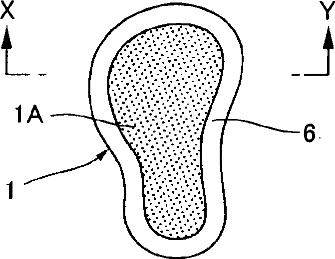
[0391] The heat generating body for heating a foot shown in FIG. 1 is a heat generating body for heating a foot having the shape of the entire foot, having a heat generating component sandwiched between a base material and a covering material, And the base material and the covering material are sealed 6 at a width of 10 mm on the periphery of the heat generating body component 1A.

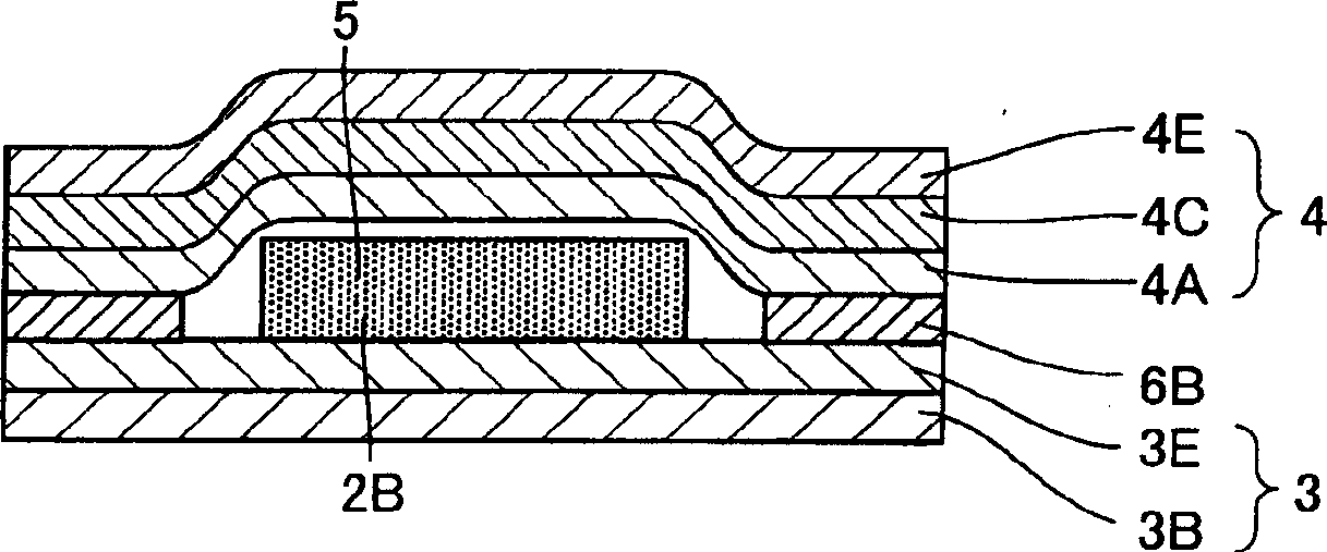
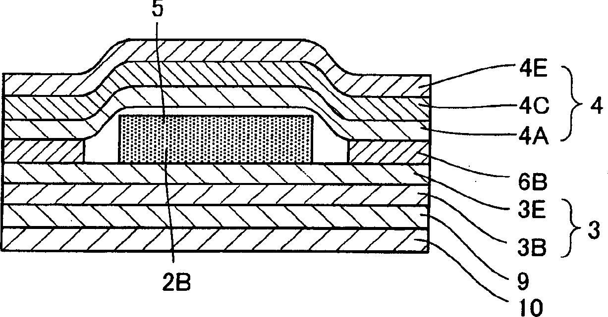
[0392] Its cross-sectional diagram is figure 2 shown in . As the base material 3, a corrugated fiberboard liner 3E having a thickness of 100 μm and a laying layer having a thickness of 50 μm and having air-impermeability and water-impermeability, made of metallocene catalyst-produced polyethylene 3B were provided. On base material 3, a non-adhesive heat-generating component with excess moisture is molded on a corrugated fiberboard liner by a mold in direct contact.

[0393] The covering material 4 is made by laminating a porous film 4C with a thickness of about 50 μm on a corrugated fiberboard li...

example 2

[0405] exist Figure 4 In the heat generating body for heating the foot shown in the plan view, the non-adhesive heat generating component with excess moisture is molded to increase the arch portion and extend from the arch portion to Example 1 by through-molding The form obtained from the shape of , and said part, except for the non-adhesive heat-generating component with excess moisture, is sealed 6 by adhesive, as in example 1.

[0406] Unlike the base material of Example 1, a rayon-polyester hybrid nonwoven fabric having a thickness of 140 μm and a rayon fiber weight of 60% was laminated on both surfaces of a polyethylene film having water absorption and a thickness of 80 μm instead of paper.

[0407] As the covering material, the same non-adhesive heat generating component with excess moisture and adhesive layer as in Example 1 were used.

example 3

[0409] exist Figure 5 In the heat-generating body for heating feet shown in the plan view of , (a) heat-generating component 1A is formed by through-molding on two areas at the approximate center of the shape as in Example 1, and except having Said part outside the non-adhesive heat-generating component 1A of excess moisture is sealed by bonding 6 . At the approximate center position where the heat generating component 1 is not laminated, the heat generating body for heating the foot can be folded so as to be compact. Since the surface area can be reduced during storage, deterioration of heat-generating components due to splashing of water can be reduced. (b) is a product that has perforated line 7A in the area without heat-generating components to facilitate folding. (c) is a product in which a portion protruding from the arched portion is increased.

[0410] The heat generating body 1 for heating the foot shown in the plan view of FIG. 6 shows Figure 5 (b) The perspect...


PUM

PropertyMeasurementUnit
diameteraaaaaaaaaa
thicknessaaaaaaaaaa
thicknessaaaaaaaaaa

Abstract

A foot warming heating element capable of preventing a heating composition from moving by fixing a part or all of the composition in a packaging materi al by using the shape maintainable heating composition and capable being suitably fitted to the shape of a foot at the time of installation to efficiently war m the specified portions of the foot for a long time irrespective of an air pressure in a storage bag when the heating element is used by sticking on th e foot, footware, and socks, characterized in that a heating formed product causing heating reaction under the presence of air and having a shape maintaining degree of 70 or higher is sealed in the storage bag formed of a substrate material and a cover material, and at least a part of the storage bag is a permeable.

Description

technical field [0001] The present invention relates to a heat-generating body for feet that supplies heat to the feet, in particular to a heat-generating body for heating the feet, which is attached to the feet, shoes or socks when in use, and has the characteristics of super Variety of shapes from thin shape to thicker shape, and can maintain the shape of the heat-generating component regardless of the pressure in the packaging bag, so that part or all of the heat-generating component can be fixed in the packaging material and can be prevented from moving , moreover, it can adapt well to the shape of the foot when it is attached, and can reach the specified temperature in a short time, effectively heat the target part for a long time, and the present invention also relates to a method for producing heated feet A process for a heat generating body that can produce a foot heat generating body in various shapes from an ultra-thin shape to a thicker shape in a simple manner at l...

Claims


Application Information

Patent Timeline
Patent Type & Authority Applications(China)
IPC IPC(8): A61F7/08A61F7/02A61F7/03C09K5/16H05B3/34H05B3/54
CPCA61N2005/066A61F2007/0098A61F7/034A61F2007/0045A61F2007/026Y10T428/24802Y10T428/2848Y10T428/24893Y10T156/1052Y10T428/24909Y10T428/28Y10T428/249994A61F7/08C09K5/16
Inventor 臼井薰相田道雄木村久雄中村正人酒卷由和百百寿浩
Owner MYCOAL
Learn More