Heat exchange device and air source heat pump system with same
A technology of heat exchange device and hot air flow, which is applied in the direction of electric heating system, heating system, hot water central heating system, etc. It can solve the problems of high air temperature and easy to produce hot feeling, and achieve noise reduction, uniform air flow, Enhance the effect of heat exchange
- Summary
- Abstract
- Description
- Claims
- Application Information
AI Technical Summary
Problems solved by technology
Method used
Image
Examples
Embodiment 1
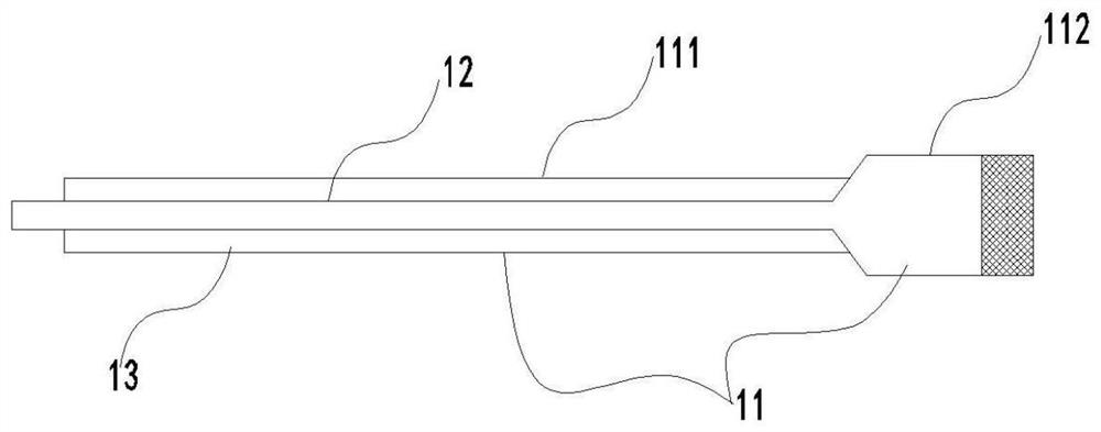
[0062] Such as figure 1 As shown, the present invention provides a heat exchange device 1, which includes: a housing 11 provided with an air inlet and an air outlet, a heat exchange body 12 arranged between the air inlet and the air outlet of the housing 11, the heat exchange The main body 12 forms a first flow path in the direction from the air inlet to the air outlet, and the first flow path flows through the heat exchange body 12 to form a heat exchange air flow; wherein, there is formed between the heat exchange body 12 and the inner wall surface of the housing 11 that does not pass through The air drainage channel 160 of the heat exchange main body 12, the air drainage channel 160 forms a second flow path from the air inlet to the air outlet, the end of the second flow path is provided with a slit outlet, and the second flow path forms a slit at the slit outlet. Slit airflow 17; the wind speed of slit airflow 17 is greater than the wind speed of heat exchange airflow; the...
Embodiment approach
[0066] Such as figure 2 and image 3 As shown, in order to improve the drainage effect of the slit airflow 17 and its mixing effect with the heat exchange airflow, it is preferred in this implementation that the air outlet includes a first air outlet and a second air outlet, and the first air outlet and the second air outlet It is arranged on the same side of the housing 11, wherein the first air outlet is used to send out the heat exchange airflow of the first flow path, and the second air outlet is used to send out the slit airflow 17 of the second flowpath, and the slit airflow (17 ) is inclined at an angle θ to the heat exchange air flow sent from the first air outlet, and the design of this angle of 0°<θ<90° increases the drainage effect of the slit airflow 17, so that after the slit airflow 17 is blown out, the A diversion airflow 18 is generated in the direction of the first air inlet and the first air outlet, and the heat exchange airflow is generated through the hea...
Embodiment 2
[0075] The air source heat pump system of this embodiment includes a compressor 4 connected by a refrigerant pipeline, an external heat exchanger 2, a flow regulating device 3, a four-way valve 5, and an internal heat exchanger, wherein the internal heat exchanger adopts a kick The heat exchanging body 12 includes only one heat exchanging unit, which is arranged along the length direction of the housing 11 . Attached below Figure 4-5 To illustrate the further optimization of this embodiment (other unclear points can adopt the same design as that of Implementation 1 within the scope understandable by those skilled in the art):
[0076] Wherein, the heat exchange device includes a housing 11 provided with an air inlet and an air outlet, and a heat exchange main body 12 arranged between the air inlet and the air outlet of the housing. The heat exchange main body 12 forms the first direction from the air inlet to the air outlet. One flow path, the first flow path flows through t...
PUM
 Abstract
Description
Claims
Application Information
 - R&D
- Intellectual Property
- Life Sciences
- Materials
- Tech Scout
- Unparalleled Data Quality
- Higher Quality Content
- 60% Fewer Hallucinations
Browse by: Latest US Patents, China's latest patents, Technical Efficacy Thesaurus, Application Domain, Technology Topic, Popular Technical Reports.
© 2025 PatSnap. All rights reserved.Legal|Privacy policy|Modern Slavery Act Transparency Statement|Sitemap|About US| Contact US: help@patsnap.com


