Eureka AIR delivers breakthrough ideas for toughest innovation challenges, trusted by R&D personnel around the world.

Insertion piece with hard metal coating

A technology of cemented carbide and inserts, which is applied in the direction of metal material coating process, coating, drilling tool accessories, etc., which can solve the problems of short tool life and plastic deformation of blades

Active Publication Date: 2004-08-04
SANDVIK INTELLECTUAL PROPERTY AB
View PDF13 Cites 13 Cited by
  • Summary
  • Abstract
  • Description
  • Claims
  • Application Information

AI Technical Summary

Problems solved by technology

Therefore tool life is usually very short when machining stainless steel
In addition, when cutting stainless steel at high cutting speeds, the thermal energy transferred to the cutting edge is very large, so the cutting edge of the tool may be partially or completely plastically deformed

Method used


Image

  • Insertion piece with hard metal coating
  • Insertion piece with hard metal coating
  • Insertion piece with hard metal coating

Examples


Embodiment 1

[0059] Inserts A and B were tested under turning conditions.

[0060] Operation: Axial and face turning of bar stock

[0061] Workpiece material: Austenitic stainless steel AISI316L

[0062] Cutting speed: 225m / min

[0063] Feed speed: 0.3mm / rotation

[0064] Cutting depth: 2.0mm

[0065] Insert model: CNMG120408-MM

[0066] Result: Tool life (minutes)

[0067] Insert A (invention): ca10

[0068] Insert B (prior art): ca6

[0069] Note: The tool life standard is that the maximum flank wear of the cutting edge line is 0.3mm. Irregular development of wear due to localized plastic deformation. This example shows an improvement in resistance to plastic deformation.

Embodiment 2

[0071] Inserts A and B were tested under turning conditions.

[0072] Operation: Intermittent cutting of assemblies

[0073] Workpiece material: Austenitic stainless steel, AISI316L

[0074] Cutting speed: 160m / min

[0075] Feed speed: 0.2-0.3mm / rev

[0076] Cutting depth: 0.5-1.5mm

[0077] Insert Model: SNMG120412-MR

[0078] Result: Tool life (minutes)

[0079] Insert A (invention): 8.2

[0080] Insert B (prior art): 4.2

[0081] Note: Wear in this test is flank wear, thermal cracking, spalling. Tool life is determined by flaking, or edge toughness. It thus exhibits improved edge toughness as well as retention of performance in other wear modes.

Embodiment 3

[0083] Inserts A and B were tested under turning conditions.

[0084] Operation: Continuous cutting of cast rings

[0085] Workpiece material: Austenitic stainless steel, AISI316L

[0086] Cutting speed: 110m / min

[0087] Feed speed: 0.3mm / rotation

[0088] Cutting depth: 3.5mm

[0089] Insert Model: CNMG120412-MR

[0090] Result: Tool life (minutes)

[0091] Insert A (invention): 18.6

[0092] Insert B (prior art): 12.4

[0093] Note: The criterion in this test is to machine through the entire part without exhibiting excessive flank wear or edge damage with a total time of 6.2 minutes in cut. The key wear criterion is the combination of flank wear and plastic deformation.

[0094] The inserts of the present invention show improvements in these respects.


PUM

PropertyMeasurementUnit
thicknessaaaaaaaaaa
thicknessaaaaaaaaaa
thicknessaaaaaaaaaa

Abstract

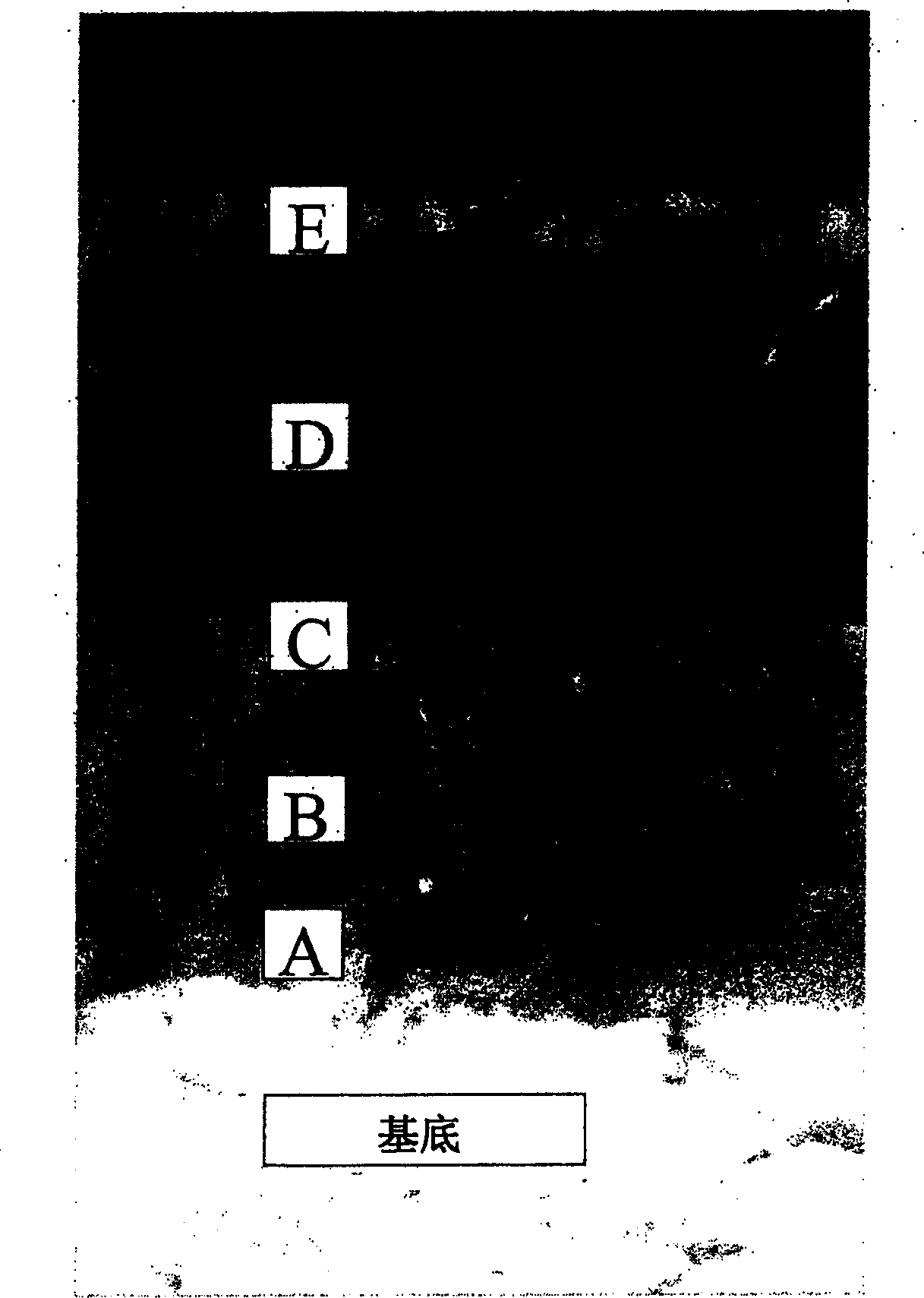
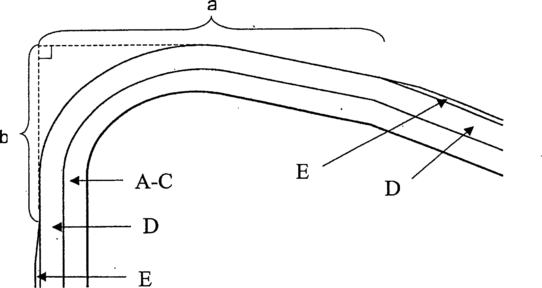
The present invention relates to a cutting tool insert particularly for turning of steel comprising a cemented carbide body, a coating with a post treatment with a first, innermost layer system of one or several layers of TiCxNyOz with x+y+z<=1 with a total thickness of 0.7-4.5 mum a second multilayer system consisting of a totally 5-31 alternating Al2O3 and TiCxNyOz (x+y+z<=1), preferably kappa-Al2O3 and TiN, the Al2O3-layers having an individual layer thickness of <0.5 mum and the TiCxNyOz-layers 0.01-0.2 mum with a total thickness of the multilayer of 1.0-4.0 mum. The multilayer is exposed along the edge line and into the rake and flank face, at least 0.02 mm, from the edge line on the rake face, preferably the contact length of the chip at most 0.9 mm, and 0.02-0.20 mm on the flank face.

Description

technical field [0001] The invention relates to a carbide-coated tool insert for machining in general steel applications where high demands are placed on the wear resistance and toughness properties of the cutting edge. This tool is especially suitable for turning stainless steel. Background technique [0002] When cemented carbide tools are used in machining steel, the tools wear due to different mechanisms such as abrasive and chemical attack, spalling and fracture of the cutting edge. The cutting of stainless steel is considered to be a particularly difficult machining operation because, in addition to the above-mentioned wear mechanisms, adhesive wear is also very prominent. Adhesive wear occurs when fouling material, such as stainless steel, continuously adheres to and tears material from the cutting edge during a cutting operation. Tool life is therefore usually very short when machining stainless steel. In addition, when cutting stainless steel at a high cutting sp...

Claims


Application Information

Patent Timeline
Patent Type & Authority Applications(China)
IPC IPC(8): B23B27/14B32B15/04C23C16/30C23C16/36C23C30/00
CPCB23B2224/04C23C30/005B23B27/145B23B2200/245Y10T428/12583B23B2228/10B23B2224/32Y10T428/265Y10T428/24975C23C28/048C23C16/36C23C28/42C23C28/044B23B27/14C23C16/40C22C27/04
Inventor 马库斯·罗得玛米卡埃尔·林霍尔姆安德斯·琼森古尼拉·安德松安德斯·努德格伦米卡埃尔·拉格尔奎斯特
Owner SANDVIK INTELLECTUAL PROPERTY AB
Why Eureka
Eureka Blog
Learn More