
Electrochemical deep etching method and apparatus thereof

A deep etching and electrochemical technology, which is applied in the field of microelectronics and microelectromechanical systems, can solve problems such as lateral erosion and structural collapse, and achieve the effects of less chemical reagents, reduced lateral erosion, and low operating costs

Inactive Publication Date: 2007-05-09
上海纳晶科技有限公司 +1
View PDF3 Cites 0 Cited by
  • Summary
  • Abstract
  • Description
  • Claims
  • Application Information

AI Technical Summary

Problems solved by technology

[0005] In addition, the direct anodic oxidation method can only obtain a pore or groove structure with a single pore size less than 5 microns, and, due to the scattering of carriers, there is lateral erosion during the anodic oxidation process when the current density is high, and in some The edge of the structure collapses, etc.
As a result, there are problems in making microsensors by using this method instead of deep reactive ion etching

Method used


Image

  • Electrochemical deep etching method and apparatus thereof

Examples


Embodiment 1

[0021] Example 1: Fabrication of silicon precision interdigitated capacitors

[0022] Silicon interdigitated capacitors are an important part of silicon inertial gyroscopes. Using high aspect ratio deep etching technology can shorten interdigital spacing, increase effective capacitance, and improve resolution. Here is an electrochemical deep etching method to make this kind of interdigitated capacitor. The layout design of the device needs to consider the size of the interdigitated capacitor. If the spacing is greater than 2 microns, it is recommended to use a method of combining small structures. In this embodiment, the spacing is 1 micron, the process steps are as follows:

[0023] The sample used in this embodiment is a silicon wafer, and the silicon wafer is an n-type silicon wafer with a resistivity of 1-5Ω·cm.

[0024] 1. Firstly, As ions are used to implant the back surface with a dose of 5×10 15 / cm 2 , the energy can be selected as 150keV, and then activated by an...

Embodiment 2

[0031] Example 2: Silicon micro-nano channel

[0032] Making micro-nano channels through up and down on silicon wafers has many uses. It can be made into micro-channel photomultiplier devices, and can also be made into filters specially used in nanobiology, such as DNA filters. In addition, it can also be As the central channel of the micro-nano needle, it is similar to Example 1. Note that if the channel density is relatively large, the requirements for the mask layer are not high, and ordinary materials such as silicon nitride, silicon carbide, and gold-chromium alloy can be used. Specifically, In terms of the fabrication of the silicon micro-nano channel in this embodiment, the silicon micro-nano channel is 0.5 μm, and the sample is also a silicon chip, and the sample silicon in Example 1 is an n-type silicon chip, and its resistivity is 1-5Ω cm, the process steps are as follows:

[0033] 1. First, As or P ions are used to implant the back surface with a dose of 5×10 15 ...


PUM

PropertyMeasurementUnit
magnetic flux densityaaaaaaaaaa
electrical resistivityaaaaaaaaaa

Abstract

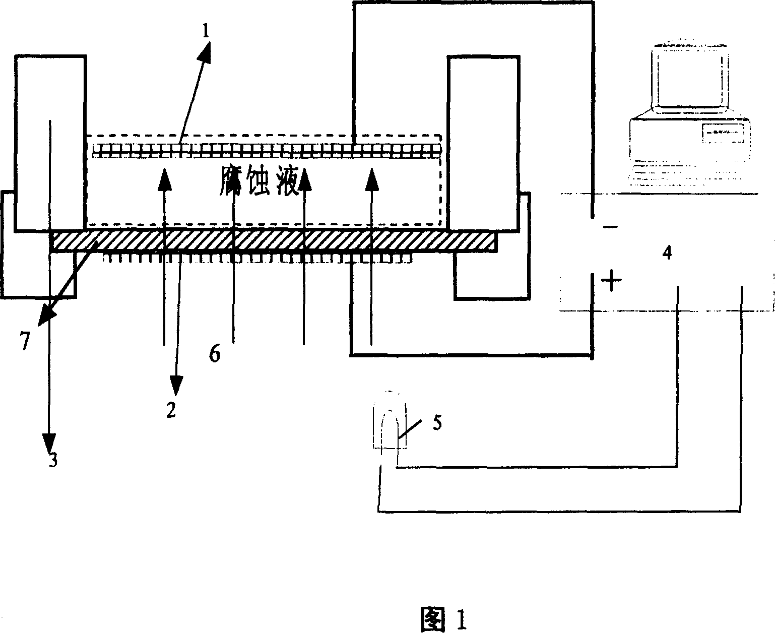
The invention relates to a produce method of a micro-electromechanical system device, especially electrochemistry deep etching, also to the processing device of the electrochemistry deep etching, belongs to the micro-electronics and micro-electromechanical system techs fields. Above method is adding magnetic field perpendicular to the sample's surface to the classic electrochemistry deep etching device, or the process takes place in a circumstance at -10 deg C up to 15 deg C. the transverse current is limited due to the effect of magnetic field so to avoid the transverse encroachment in the anodizing and collapse on the edge of some certain structure. Controlling the temperature lowers the crystal lattice scattering rate of the dispersing stream particles which makes the etching much more remarkable.

Description

technical field [0001] The invention relates to a manufacturing method of a microelectromechanical system device, in particular to an electrochemical deep etching method and a device for the electrochemical deep etching method, belonging to the technical fields of microelectronics and microelectromechanical systems. Background technique [0002] In microelectromechanical systems (collectively referred to as "MEMS" hereinafter), the deep etching technology of silicon is of great significance. Usually, sensors of mechanical quantities such as gyroscopes, acceleration sensors, and pressure sensors can be made by deep etching of silicon, and deep holes or trenches that can be used for through-hole interconnection of RF MEMS can also be made by using deep etching technology, or used to make micro-electromechanical systems. fluid structure. [0003] At present, the main method for deep etching of silicon is deep reactive ion etching, also known as plasma ...

Claims


Application Information

Patent Timeline
Patent Type & Authority Patents(China)
IPC IPC(8): B81C1/00
Inventor 王连卫陈瑜赖宗声
Owner 上海纳晶科技有限公司
Learn More