Microflute evaporating and cooling method and apparatus using same
A technology of evaporative cooling and cooling method, which is applied in the field of evaporative cooling method of computer chip and its device, can solve the problems of large heat dissipation area, insufficient heat dissipation capacity, small heat dissipation area, heat flux density and total heat dissipation capacity, etc., and achieve the improvement of total heat dissipation capacity , Improve working performance, no power consumption heat dissipation and cooling effect
- Summary
- Abstract
- Description
- Claims
- Application Information
AI Technical Summary
Problems solved by technology
Method used
Image
Examples
Embodiment 1
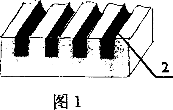
[0030] Embodiment 1: A lot of rectangular micro-grooves 2 are carved on a metal plate or other heat-conducting materials to form a micro-groove group. This heat exchange structure with micro-groove groups is called a micro-groove group heat sink, as shown in FIG. 1 . In Fig. 1, the microchannels 2 are vertically densely arranged. The channel width and channel depth of the micro-channel 2 are in the range of 0.01-1 mm, and are rectangular micro-channels. The distance between the micro-channels is in the range of 0.01-10mm. The micro-channels 2 in this range have capillary attraction for various working fluids such as absolute ethanol or distilled water. More optimally, the width of the micro-channels and The depth is in the range of 0.01-0.6mm, and the distance between the micro-channels is in the range of 0.01-10mm. When the metal plate and the heating element are closely pasted by heat-conducting silica gel (silicon grease), the heat generated by the heating element is trans...
Embodiment 2
[0031] Embodiment 2: Directly engrave many microgrooves 2 on the outer surface of chips or other heating elements to form microgrooves groups, and the parts carved with microgrooves of heating elements such as chips become heat sinks of microgrooves groups. The size of the microchannel of the present embodiment is the same as that of embodiment 1, and the microchannel has capillary force equally, so that the liquid working medium is sucked into the heated area in the microchannel 2 and evaporated so as to take away the heat generated by heating elements such as chips.
Embodiment 3
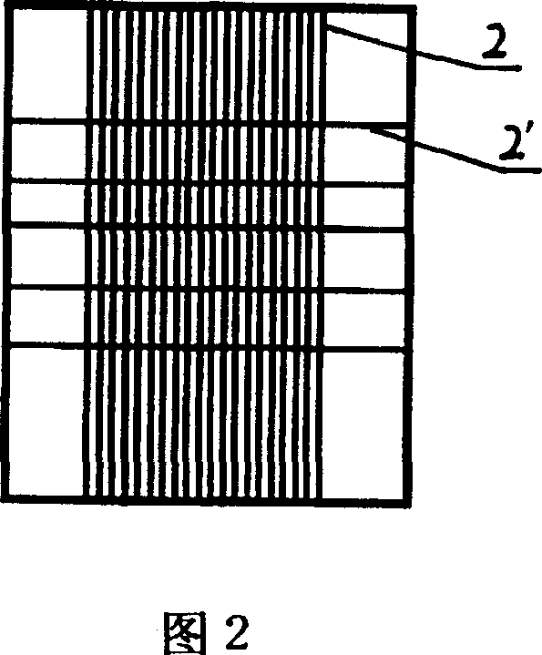
[0032] Embodiment 3: see Fig. 2: the micro-grooves 2 of present embodiment micro-groove group heat sink are vertically densely arranged, and the micro-grooves 2 arranged vertically are cross-arranged with horizontal micro-grooves 2'. Arranging the microchannels 2' arranged horizontally can absorb more liquid working fluid to the heating area, so that the evaporated liquid working medium can be replenished in time, thereby improving the cooling efficiency. In this embodiment, the groove width of the microchannel 2 is 0.2mm, the groove depth is 0.5mm, and the groove spacing is 0.2mm, and the groove width of the transverse microchannel 2' is 0.4mm, the groove depth is 0.8mm, and the groove spacing is 5mm.
PUM
 Abstract
Description
Claims
Application Information
 - R&D
- Intellectual Property
- Life Sciences
- Materials
- Tech Scout
- Unparalleled Data Quality
- Higher Quality Content
- 60% Fewer Hallucinations
Browse by: Latest US Patents, China's latest patents, Technical Efficacy Thesaurus, Application Domain, Technology Topic, Popular Technical Reports.
© 2025 PatSnap. All rights reserved.Legal|Privacy policy|Modern Slavery Act Transparency Statement|Sitemap|About US| Contact US: help@patsnap.com


