Apparatus of water draining for gas pipeline

A technology for drainage devices and gas pipelines, applied in pipeline systems, gas/liquid distribution and storage, mechanical equipment, etc., can solve the problems of uncoordinated beautiful environment, large investment, short working life, etc., and improve work safety and reliability. , to ensure the effect of work safety, work safety and reliability

Inactive Publication Date: 2006-09-06
赵建华
View PDF0 Cites 0 Cited by
  • Summary
  • Abstract
  • Description
  • Claims
  • Application Information

AI Technical Summary

Problems solved by technology

[0004] 1. The device is exposed, affecting the environment and occupying a large area
The total height of the drains is about 2.5 meters and all of them are exposed above the ground. They are big, dark and thick, which are extremely incompatible with the beautiful environment and occupy a large area.
[0005] 2. High energy consumption
In order to prevent freezing in winter, it is necessary to lay steam heating pipes (or use electric insulation) along the entire length of the pipeline. Not only the drain itself consumes a lot of energy, but also the heat loss of the steam main pipe along the line is serious, which requires a large investment and high cost.
[0006] 3. Short working life and poor safety
The average service life of steel drains is only 6 years

Method used


Image

  • Apparatus of water draining for gas pipeline
  • Apparatus of water draining for gas pipeline
  • Apparatus of water draining for gas pipeline

Examples


Embodiment Construction

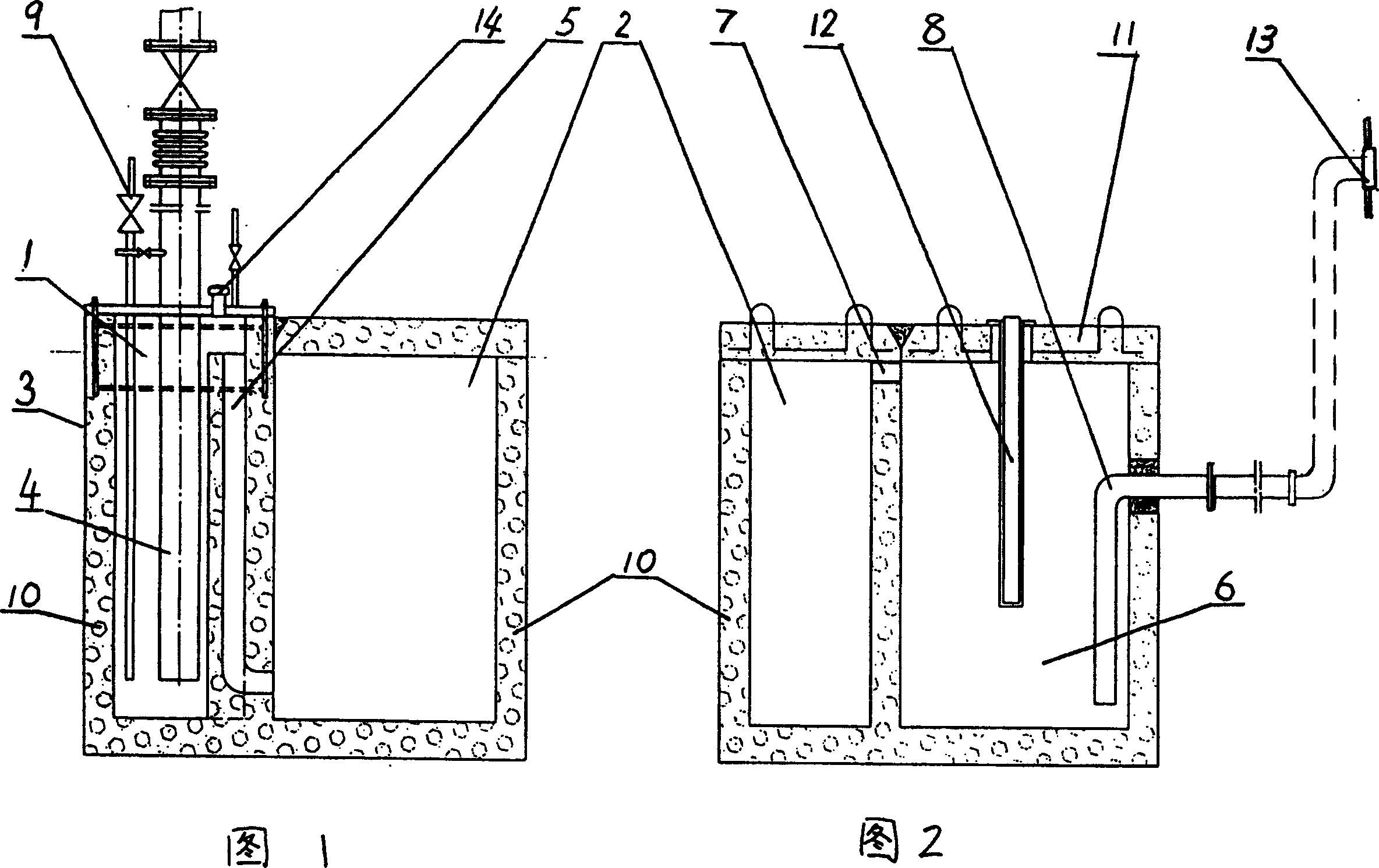
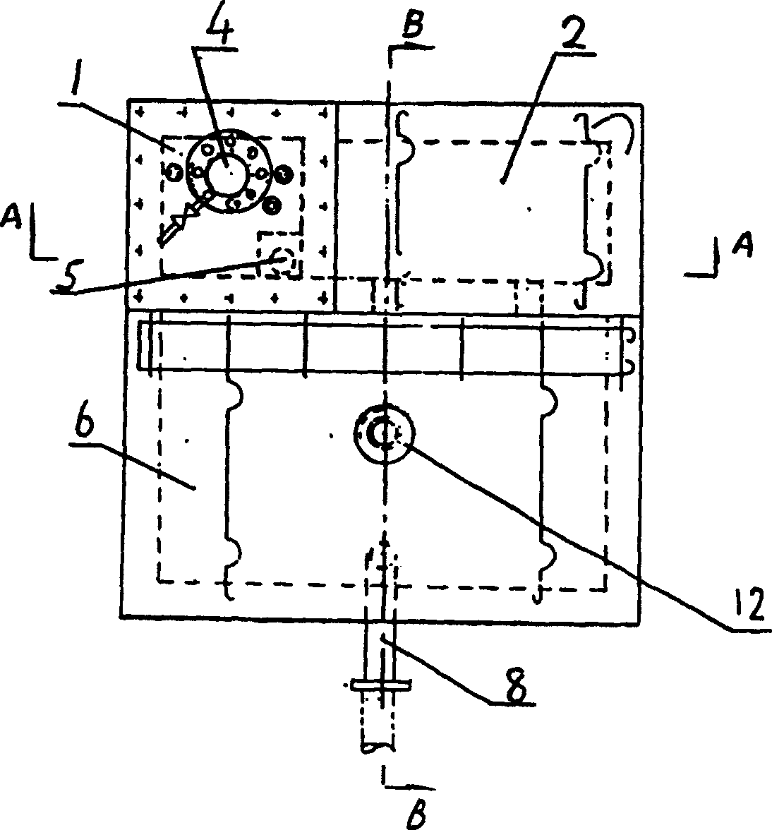
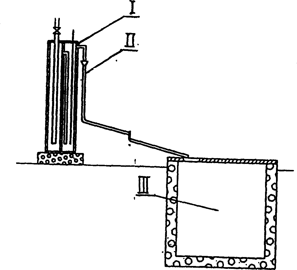
[0025] As shown in Figures 1, 2, and 3, a drainage device for a gas pipeline includes: a vertical drain and a sump. The vertical drain is divided into a high-pressure water seal chamber 1, a low-pressure water seal chamber 2, and a high-pressure water seal A high-pressure water-seal pipe 4 connected with the gas pipe network is inserted into the chamber 1, the low-pressure water-seal chamber 2 is connected to the low-pressure water-seal pipe 5, and the upper part of the low-pressure water-seal chamber 2 is connected to the sump through a drain pipe. The drain 3 and the sump 6 composed of the high-pressure water-sealing chamber 1 and the low-pressure water-sealing chamber 2 are designed as an integral structure and placed below the ground. The bottom of the high-pressure water-sealing chamber 1 is sealed by a low-pressure water-sealing pipe 5 It is connected with the low-pressure water-sealed chamber 2, and the upper part of the low-pressure water-sealed chamber 2 is in communicati...


PUM


Abstract

The invention refers to a drainage device of gas conduit condensate. The existing drainage device is steeliness barrel shaped drainage device. It has disadvantages of device discovered, environment influenced, large land occupied, high energy consumed, short useful life and low reliablity. The invention supplies a drainage device for gas conduit that includes vertical drainer and stagnant pool. The drainer, made up of high pressure water sealed room and low pressure water sealed room, is integrated together with stagnant pool. It is located underground. The body of it is made up of heat-insulated and corrosion resisted concrete. The low pressure water sealed pipe connects the bottom of the high pressure water sealed room and low pressure water sealed room. The top of the low pressure water sealed room is connected to stagnant pool through condensation overflow pipe that is made up of corrosion resisted engineering plastic. And it is constructed into concrete wall. The invention has the advantages of high safety and reliability, long useful life, low energy consumption and good environment consistency.

Description

Technical field [0001] The invention relates to a metallurgical and chemical enterprise, an automatic discharge device for mechanical water in flammable, explosive and toxic gases, and condensate in a gas transportation process, and is particularly suitable for the discharge of condensate in a gas pipeline. Background technique [0002] In the dangerous gases of various gas and chemical enterprises, there is inevitably a part of mechanical water and saturated water, which continuously precipitate as the gas flow rate and temperature decrease, causing a large amount of condensate in the gas pipeline, which contains SO 4 2- , Cl - , H 2 S, etc. will produce strong chemical corrosion and electrochemical corrosion on metal components. To ensure the safety of the pipeline, various drains are widely used to automatically discharge the condensate. [0003] For condensate discharge from gas pipes, traditional drainage devices have been used for decades. Such as Figure 4 As shown, it is...

Claims


Application Information

Patent Timeline
Patent Type & Authority Patents(China)
IPC IPC(8): F17D3/14
Inventor 赵建华张玉萍赵圣娟赵圣赜
Owner 赵建华
Why Eureka
Try Eureka