Receiving antenna of optical communication system

A communication system and receiving antenna technology, applied in the field of optical communication systems, can solve the problems of difficulty in adjusting the detector and the receiving optical system, affecting the performance of the system, and being in vain, achieving simple and easy adjustment of the optical path, expanding the receiving aperture, and the ability to interfere. Enhanced effect

Inactive Publication Date: 2005-05-25
NANJING UNIV
View PDF0 Cites 0 Cited by
  • Summary
  • Abstract
  • Description
  • Claims
  • Application Information

AI Technical Summary

Problems solved by technology

In short, the problems of direct reception with optical signal detectors are: 1. When the receiving area of ​​the detector is smaller than the light spot, a large amount of light energy will be lost, resulting in shorter system transmission distance and lower signal-to-noise ratio, which seriously affects system performance; The faster the speed, the more obvious the impact
2. The coordination and adjustment of the detector and the receiving optical system is extremely difficult. Even after the adjustment and installation are completed, the detector will deviate from the position of the beam waist under the influence of vibration, which will seriously damage the system performance.
3. The influence of the receiving effect at the detector end is far greater than that of the optical antenna at the sending end, the optical system at the receiving end, and the laser. In extreme cases, the efforts of the current FSO manufacturers in the work described below will be in vain.

Method used


Image

  • Receiving antenna of optical communication system
  • Receiving antenna of optical communication system
  • Receiving antenna of optical communication system

Examples


Embodiment Construction

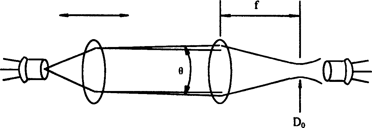
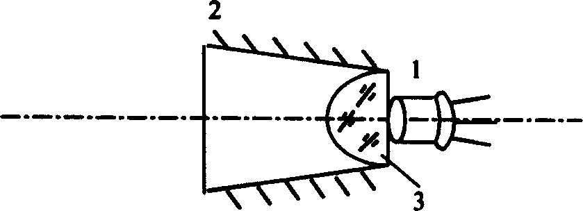
[0022] The receiving antenna of the optical communication system designed in the present invention, wherein the detector receiving part includes a detector 1 , a hollow light cone 2 and an immersion lens 3 . The production steps are: determine D according to the overall design requirements of the system 0 , f, θ and other parameters. press D 0 , f, θ * (the beam divergence angle after the focusing of the receiving optical system) and the size of the detector 1 are designed to manufacture the hollow light cone 2 and the immersion lens 3 . The hollow light cone 2 and the immersion lens 3 are combined, calibrated with a standard light source and fixed mechanically. The surface of the detector 1 is placed close to the rear surface of the immersion lens 3 and placed on the optical axis of the combined hollow light cone 2 and immersion lens 3, calibrated with a standard light source, bonded and cured with high refractive index glue.


PUM


Abstract

The character of the optical receiving antenna is that it also contains a detector and a light cone and an immersion lens. The immersion lens is positioned at the small end of the light cone, and thedetector is positioned at the back surface of the immersion lens. The large end of the optical cone is located near the focal plane of the optical system so as to extend receive aperture, increase the light energy entered to the system. Large aperture makes the detector insensitivity to the focal point. Thus, the optical path is easy to be adjusted, increasing the capability of anti vibration. The immersion lens raises the receiving visual angle of the detector, making the small detector receive optical signal from larger area of visual field so as to obtain high S / N ratio. Moreover, the immersion lens shortens the length of FSO system making structure compact.

Description

1. Technical field [0001] The invention relates to an optical communication system, in particular to a receiving antenna which adopts an auxiliary optical system to improve the receiving performance of optical signals, which is suitable for but not limited to a free space optical communication system (FSO). 2. Background technology [0002] Optical fiber communication and wireless communication are currently popular technologies, and the free space optical communication system is the product of the combination of the two. It has some advantages of optical fiber communication and some advantages of wireless communication. Compared with these two technologies, its unique features are as follows: [0003] Compared with radio communication (such as microwave): it does not occupy valuable radio frequency resources; it has good electromagnetic compatibility, strong anti-electromagnetic interference ability, and good confidentiality; it has large information capacity; it is small i...

Claims


Application Information

Patent Timeline
Patent Type & Authority Patents(China)
IPC IPC(8): G02B7/02H01Q15/02H04B10/11
Inventor 许国良张旭苹黄金源
Owner NANJING UNIV
Why Eureka
Try Eureka