Touch control module and sensing device

A technology of a touch module and a sensing device, which is applied in the directions of instruments, electrical digital data processing, and data processing input/output processes, etc., can solve the problems of poor alignment accuracy between the plug-in module 110 and the light guide plate 130, and achieves Effect of increasing sensing acuity

Inactive Publication Date: 2015-03-25
AU OPTRONICS CORP
View PDF2 Cites 0 Cited by
  • Summary
  • Abstract
  • Description
  • Claims
  • Application Information

AI Technical Summary

Problems solved by technology

However, since the plug-in module 110 and the light guide plate 130 are configured on the frame, and the relative positions of the plug-in module 110 and the light guide plate 130 are determined according to the design of the frame, when the manufacturing tolerance of the frame is large, it will cause The problem of poor alignment accuracy between the plug-in module 110 and the light guide plate 130

Method used


Image

  • Touch control module and sensing device
  • Touch control module and sensing device
  • Touch control module and sensing device

Examples


no. 1 example

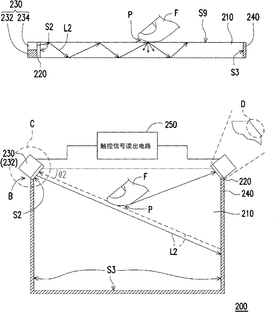
[0068] figure 2 It is a schematic diagram of a touch module (touch module) according to the first embodiment of the present invention, wherein figure 2 The top of is the cross-sectional view of the touch module, while figure 2 Below is the top view of the touch module. Please refer to figure 2The touch module 200 of this embodiment includes a light guide plate 210 , an optical glue 220 , a touch sensing module 230 and a retro-reflector 240 . The light guide plate 210 has an end surface S2 and a plurality of optical surfaces S3. The touch sensing module 230 is disposed on the end surface S2 , and the touch sensing module 230 includes a sensing component 232 and a light source 234 . In addition, the light guide plate 210 further has a top surface S9, and the end surface S2 and the optical surface S3 are substantially perpendicular to the top surface S9. Additionally, if figure 2 As shown below, the end surface S2 is an inclined plane. In detail, the end surface S2 of...

no. 2 example

[0077] Figure 5 It is a schematic diagram of a touch module according to the second embodiment of the present invention, wherein Figure 5 The top of is the cross-sectional view of the touch module, while Figure 5 Below is the top view of the touch module. Please refer to Figure 5 , the touch module 400 of this embodiment and figure 2 The touch module 200 is similar, but the main difference between the two is: the touch module 400 does not use figure 2 Instead, the light source 234' is directly disposed on the optical surface S3, wherein the light source 234' is a plurality of light bars.

[0078] Such as Figure 5 As shown, the light source 234' is adapted to provide light L2 into the light guide plate 210, and the sensing element 232' is adapted to receive the light L2 transmitted through the light guide plate 210. When the user touches the light guide plate 210 with a finger F or a stylus, the light L2 near the touch point P will be scattered, and the above-menti...


PUM


Abstract

The invention relates to a touch control module which comprises a light guide plate, an optical adhesive material and a touch control sensing module, wherein the light guide plate is provided with an end surface and a plurality of optical surfaces; the touch control sensing module is arranged on the end face and comprises a sensing assembly and a light source; the sensing assembly is adhered on the end surface of the light guide plate through the optical adhesive material; the light source is used for providing light to the light guide plate and arranged on the optical surfaces or the end surface; and the sensing assembly is suitable for receiving light transmitted by the light guide plate. The invention also provides a sensing device.

Description

【Technical field】 [0001] The present invention relates to a touch module and a sensing device, and in particular to an optical touch module and a sensing device. 【Background technique】 [0002] According to different sensing methods, touch panels can be roughly divided into resistive touch panels, capacitive touch panels, optical touch panels, acoustic touch panels, and electromagnetic touch panels. Since the touch mechanism of the optical touch panel is suitable for large-size display panels, the touch function of the large-size display panel is mostly achieved through the optical touch mechanism. [0003] Most of the current optical touch display panels use infrared light as a light source, and use a complementary metal oxide semiconductor photosensor (CMOS optical sensor) to sense the infrared light. For example, manufacturers have integrated infrared light-emitting diodes (IR-LEDs) capable of emitting infrared light and complementary metal oxide semiconductor photosenso...

Claims


Application Information

Patent Timeline
Patent Type & Authority Patents(China)
IPC IPC(8): G06F3/042
Inventor 简智伟蔡卲瑜
Owner AU OPTRONICS CORP
Why Eureka
Try Eureka