Infrared transmitting device, infrared receiving device and infrared transceiving system

A technology of receiving device and transmitting device, which is applied in the direction of transmission system, electromagnetic transmitter, electromagnetic receiver, etc., can solve the problem that the angle of infrared emission and reception is not large, and achieve the effect of improving the angle of emission and reception

Inactive Publication Date: 2010-06-23
SICHUAN COC DISPLAY DEVICES
View PDF3 Cites 4 Cited by
  • Summary
  • Abstract
  • Description
  • Claims
  • Application Information

AI Technical Summary

Problems solved by technology

[0011] The purpose of the present invention is to provide an infrared emitting device, an infrared receiving device and an infrared transceiver system, which can solve the problems in the related art that the infrared emitting and receiving angles are not large.

Method used


Image

  • Infrared transmitting device, infrared receiving device and infrared transceiving system
  • Infrared transmitting device, infrared receiving device and infrared transceiving system
  • Infrared transmitting device, infrared receiving device and infrared transceiving system

Examples


Embodiment Construction

[0022] The present invention will be described in detail below with reference to the accompanying drawings and in combination with embodiments.

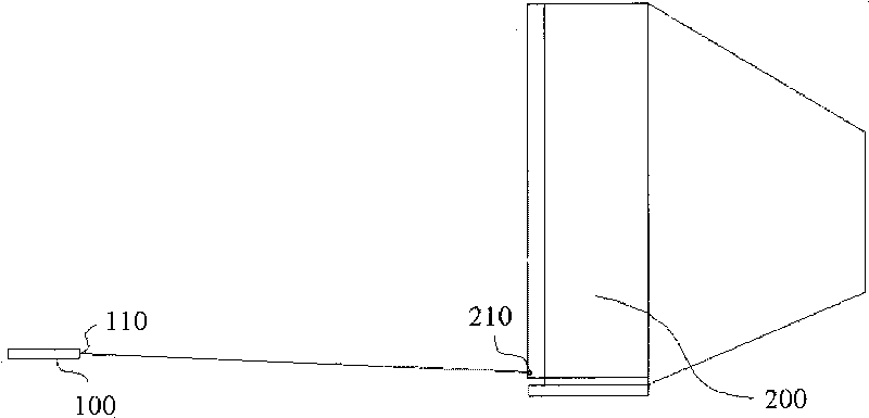
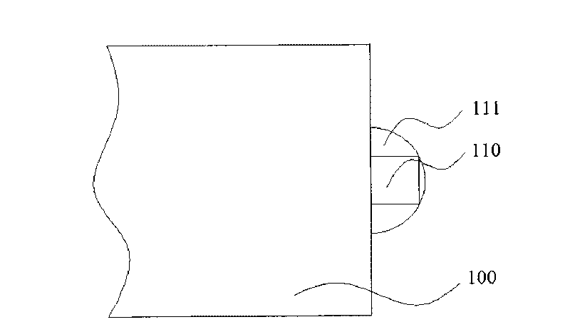
[0023] figure 2 is a partially enlarged schematic diagram of an infrared emitting device according to an embodiment of the present invention. Such as figure 2 As shown, the infrared emitting device 100 includes: an infrared emitting module 110 and a light-scattering crystal plate 111 located on the outer surface of the infrared emitting module 110 . When the infrared ray emitting module 110 emits the infrared ray control signal, the diffuser crystal plate 111 disperses the emitted infrared ray control signal so as to increase the emission angle of the infrared ray control signal. According to the design requirements, the remote control of the transmitter can be realized at a maximum of 360 degrees.

[0024] In this embodiment, the astigmatism component located on the outer surface of the infrared emitting module 110 is a astigma...


PUM


Abstract

The invention provides an infrared transmitting device, an infrared receiving device and an infrared transceiving system, wherein the infrared transmitting device comprises an infrared transmitting module and a light-scattering module which is arranged on the outer surface of the infrared transmitting module and used for scattering the infrared rays transmitted by the infrared transmitting module. As the infrared transmitting device is provided with a light-scattering crystal wafer, and the infrared receiving device is provided with a light-gathering crystal wafer, thereby improving the infrared transmitting and receiving angles. Furthermore, the light-gathering crystal wafer in the infrared receiving device and the infrared receiving module are arranged at the bottom of the infrared receiving device and protrude downwards from the bottom surface of the infrared receiving device, thereby receiving the infrared rays coming from 360 degrees.

Description

technical field [0001] The invention relates to the field of remote control, and more specifically, to an infrared emitting device, an infrared receiving device and an infrared transceiver system. Background technique [0002] Commonly used infrared remote control systems are generally divided into two parts: transmitting and receiving. The main components of the emitting part are infrared light emitting diodes. It is actually a special light-emitting diode. Because its internal material is different from ordinary light-emitting diodes, when a certain voltage is applied to its two ends, it emits infrared rays instead of visible light. [0003] The main factors affecting the Remote distance of RF Remote Control are as follows: [0004] 1. Transmitting power: High transmitting power means long distance, but it consumes a lot of power and is prone to interference; [0005] 2. Receiving sensitivity: The receiving sensitivity of the receiver is improved, and the remote control...

Claims


Application Information

Patent Timeline
Patent Type & Authority Applications(China)
IPC IPC(8): H04B10/02H04B10/10H04B10/50H04B10/60
Inventor 陈立国
Owner SICHUAN COC DISPLAY DEVICES
Why Eureka
Try Eureka