Numerical control machine tool machining center capable of conveniently clamping special-shaped workpiece

一种异形工件、数控机床的技术,应用在全面工厂控制、金属加工设备、金属加工机械零件等方向,能够解决异形工件夹持不稳固、降低数控加工精确性、不便工件观察等问题,达到方便观察、适配度高、便于观察的效果

Inactive Publication Date: 2022-07-29
RIZHAO FANGLE PRECISION MASCH CO LTD
View PDF5 Cites 0 Cited by
  • Summary
  • Abstract
  • Description
  • Claims
  • Application Information

AI Technical Summary

Problems solved by technology

[0003] There are still some deficiencies in the existing CNC machining. First of all, most of the workpieces are limited and fixed by weldments, fixing sleeves or limit plates at present, but there are still some unstable phenomena in the clamping of special-shaped workpieces. The accuracy of CNC machining is reduced; secondly, the interior of the existing CNC machining center lacks lighting devices, which is not convenient for operators to observe the processing status of workpieces and affects the processing quality

Method used


Image

  • Numerical control machine tool machining center capable of conveniently clamping special-shaped workpiece
  • Numerical control machine tool machining center capable of conveniently clamping special-shaped workpiece
  • Numerical control machine tool machining center capable of conveniently clamping special-shaped workpiece

Examples


Embodiment 1

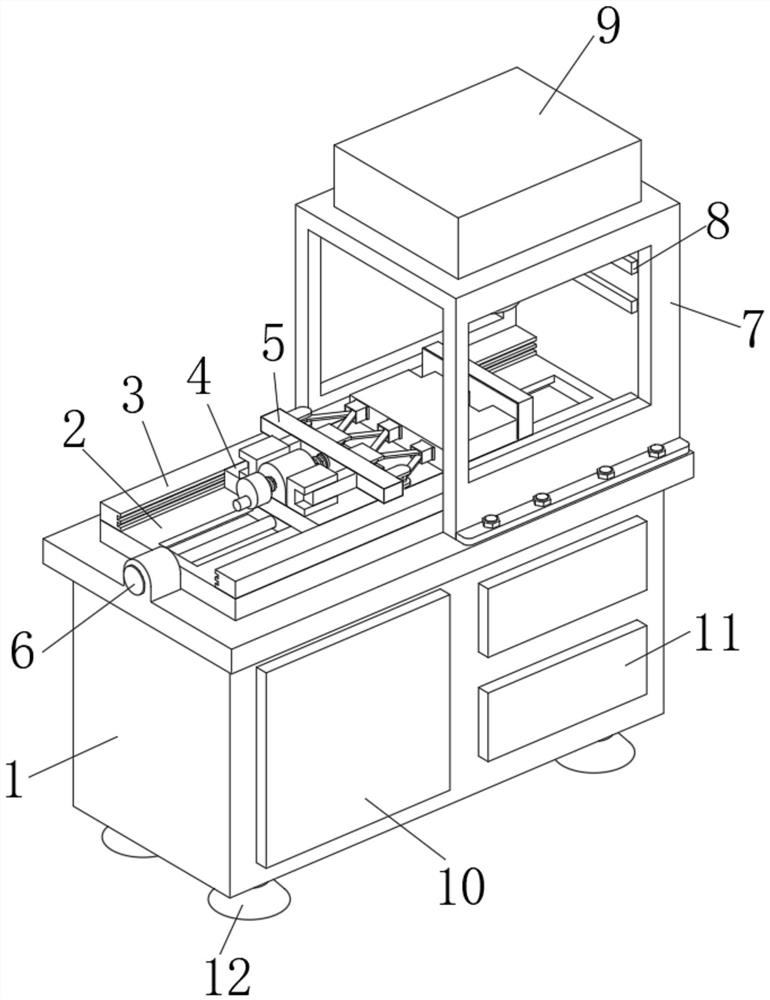
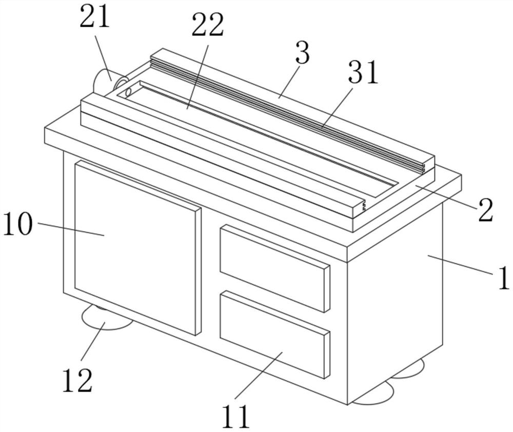
[0034]A CNC machine tool machining center that is convenient for clamping special-shaped workpieces, such as Figure 1-2 As shown, it includes an operating table 1, a fixed backing plate 2 is fixedly installed in the middle of the upper end of the operating table 1, a fixed seat 21 is fixedly welded on the left end of the fixed backing plate 2, and a chute 22 is opened in the middle of the upper end of the fixed backing plate 2 , a side support plate 3 is fixedly installed on the front and rear sides of the upper end of the fixed backing plate 2, two sliding rails 31 are opened on the opposite ends of the two side support plates 3, and a moving mechanism 4 is slidably connected in the sliding groove 22. And the front and rear ends of the moving mechanism 4 are slidably connected with the slide rails 31, an electric telescopic rod 6 is fixedly installed in the fixed seat 21, and the electric telescopic rod 6 is fixedly connected with the left end of the moving mechanism 4, and t...

Embodiment 2

[0037] On the basis of Example 1, as Figure 3-7 As shown, a CNC machine tool machining center that is convenient for clamping special-shaped workpieces includes an operation table 1, a fixed backing plate 2 is fixedly installed in the middle of the upper end of the operating table 1, and a fixed seat 21 is fixedly welded on the left end of the fixed backing plate 2. A chute 22 is opened in the middle of the upper end of the fixed backing plate 2 , a side support plate 3 is fixedly installed on the front and rear sides of the upper end of the fixed backing plate 2 , and two sliding rails 31 are opened on the opposite ends of the two side support plates 3 . A moving mechanism 4 is slidably connected in the chute 22, and the front and rear ends of the moving mechanism 4 are slidably connected with the slide rail 31. An electric telescopic rod 6 is fixedly installed in the fixed seat 21, and the electric telescopic rod 6 is connected with the moving mechanism 4. The left end of t...

Embodiment 3

[0040] On the basis of Example 1, as Figure 8 As shown, a CNC machine tool machining center that is convenient for clamping special-shaped workpieces includes an operation table 1, a fixed backing plate 2 is fixedly installed in the middle of the upper end of the operating table 1, and a fixed seat 21 is fixedly welded on the left end of the fixed backing plate 2. A chute 22 is opened in the middle of the upper end of the fixed backing plate 2 , a side support plate 3 is fixedly installed on the front and rear sides of the upper end of the fixed backing plate 2 , and two sliding rails 31 are opened on the opposite ends of the two side support plates 3 . A moving mechanism 4 is slidably connected in the chute 22, and the front and rear ends of the moving mechanism 4 are slidably connected with the slide rail 31. An electric telescopic rod 6 is fixedly installed in the fixed seat 21, and the electric telescopic rod 6 is connected with the moving mechanism 4. The left end of the...


PUM


Abstract

The numerical control machine tool machining center comprises an operation table, a fixed base plate is fixedly mounted in the middle of the upper end of the operation table, side supporting plates are fixedly mounted on the front side and the rear side of the upper end of the fixed base plate correspondingly, and two sliding rails are formed in the opposite ends of the two side supporting plates correspondingly; a moving mechanism is slidably connected into the sliding groove, the front end and the rear end of the moving mechanism are slidably connected with the sliding rails, an electric telescopic rod is fixedly installed in the fixing base and fixedly connected with the left end of the moving mechanism, and the left side of the upper end of the moving mechanism is in threaded connection with a positioning mechanism. A protection frame is detachably installed on the right side of the upper end of the operation table, and three lighting mechanisms are detachably installed at the right end of the protection frame. Three contact surfaces of a special-shaped workpiece can be fixed at the same time, the operation safety is high, the illumination function is achieved, observation is convenient, and dismounting and mounting are convenient.

Description

technical field [0001] The invention relates to the field of numerical control machining equipment, in particular to a numerical control machine tool machining center which is convenient for clamping special-shaped workpieces. Background technique [0002] CNC machining refers to a process method for processing parts on CNC machine tools. The process rules of CNC machine tool processing and traditional machine tool processing are generally consistent, but there have also been significant changes. Digital information is used to control parts and components. The machining method of tool displacement is an effective way to solve the problems of variable variety of parts, small batches, complex shapes and high precision, and to achieve efficient and automated processing. [0003] There are still some shortcomings in the existing CNC machining. First of all, most of the workpieces are limited and fixed by welding parts, fixed sleeves or limit plates, but there are still some unst...

Claims


Application Information

Patent Timeline
Patent Type & Authority Applications(China)
IPC IPC(8): B23Q3/06
CPCB23Q3/065Y02P90/02
Inventor 费聿娟
Owner RIZHAO FANGLE PRECISION MASCH CO LTD
Why Eureka
Try Eureka