
Microgroove group heat dissipation device with porous medium material and heat dissipation method

A technology of porous medium and heat dissipation device, which is applied in the direction of cooling/ventilation/heating transformation, semiconductor/solid-state device parts, semiconductor devices, etc., which can solve the problems of inability to contact the phase-change working medium in the radiator, and improve the liquid filling rate Effect

Pending Publication Date: 2022-07-12
INST OF ENGINEERING THERMOPHYSICS - CHINESE ACAD OF SCI +1
View PDF0 Cites 0 Cited by
  • Summary
  • Abstract
  • Description
  • Claims
  • Application Information

AI Technical Summary

Problems solved by technology

[0005] Purpose: In order to overcome the deficiencies in the prior art, the present invention provides a method of using porous dielectric materials to solve the problem that the micro-groove group heat sink in the current traditional bottom-emitting LED micro-groove group heat sink cannot contact and dissipate heat at a certain inclination and rotation angle. Liquid replenishment of phase change working medium in the device to improve the adaptability of micro-groove group heat sinks to tilt and rotation angles in practical applications

Method used


Image

  • Microgroove group heat dissipation device with porous medium material and heat dissipation method
  • Microgroove group heat dissipation device with porous medium material and heat dissipation method
  • Microgroove group heat dissipation device with porous medium material and heat dissipation method

Examples


Embodiment 1

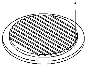
[0031] In the micro-groove group radiator with porous dielectric material in this embodiment, the main radiator 1 is provided with a vacuum cavity 5 and filled with a certain amount of phase change working medium. The fin group 2 is installed on the main body radiator 1 by a plurality of fin monomers at equal intervals. The porous medium material 3 is a ceramic porous material or a foamed metal material and is closely attached around the heat sink 4 of the micro-groove group. The micro-groove group heat sink 4 is arranged at the bottom of the main body heat sink 1 and is connected to the bottom of the vacuum chamber 5 . The heat source is tightly fixed on the bottom surface of the heat sink 4 of the micro-groove group through thermal interface materials such as thermally conductive silicone grease or thermally conductive silicone pad.

[0032] like figure 1 As shown, the main radiator 1 is a sunflower radiator, with an outer diameter of 20-200mm and a height of 20-200mm, and...

Embodiment 2

[0034] like figure 2 As shown in the figure, a micro-groove group radiator with porous dielectric material in this embodiment is further improved on the basis of Embodiment 1. The shape of the porous dielectric material 3 is a circular ring, and the size is an inner diameter of 15~190mm. , The outer diameter is 20~200mm, the height is 1~5mm, and the material is ceramic or foam metal, which is used to absorb the phase change working medium. Ceramic porous materials have the advantages of low price, long service life, light weight, and anti-oxidation; foam metal has the advantages of controllable porosity, stable structure, and high temperature resistance. Both materials can be in close contact with the heat sink 4 of the microgroove group.

Embodiment 3

[0036] like Figure 3-5As shown, a micro-groove group heat sink with porous dielectric material in this embodiment is further improved on the basis of Embodiment 2, in order to make the porous dielectric material 3 and the micro-groove group heat sink 4 in close contact. The heat sink 4 of the micro-groove group is designed to be concentric cylinders with different diameters, and the radius of the upper cylinder is smaller than the radius of the lower cylinder. Among them, the outer diameter of the upper cylinder is 15~190mm, the height is 1~5mm, the outer diameter of the lower cylinder is 20~200mm, and the height is 1~15mm, and the upper surface has evenly distributed micro-channels, including N, of which N≥10, the arrangement density More than 2 pieces / cm, the cross section of the micro channel is rectangular, triangular, trapezoidal or other irregular shapes, and the dimensions are: groove width 20~5000µm, groove depth 20~5000µm, groove spacing 20~5000µm. The assembly of t...


PUM


Abstract

The invention provides a microgroove group heat dissipation device with a porous medium material and a heat dissipation method, and the device comprises a main body radiator which is internally provided with a vacuum cavity, and the vacuum cavity is filled with a phase change working medium; the fin group is arranged outside the main body radiator and comprises a fin radiator; the microgroove group heat sink is arranged at the bottom of the main body radiator and is connected with the bottom of the vacuum cavity; the porous medium material is fixedly arranged between the micro-groove group heat sink and the main body radiator, the phase change working medium is kept in contact with a micro-groove channel in the micro-groove group heat sink through the porous medium material, the phase change working medium is kept in contact with the micro-groove channel in the micro-groove group heat sink through the porous medium material, and the phase change working medium is in contact with the micro-groove channel in the micro-groove group heat sink under a certain liquid filling rate. The bottom-emitting LED micro-groove group radiator can adapt to inclination and rotation angles in any direction, and therefore the liquid supplementing problem that a micro-groove group heat sink in an existing traditional bottom-emitting LED micro-groove group radiator cannot make contact with a phase change working medium in the radiator under the condition of certain inclination and rotation angles is solved.

Description

technical field [0001] The invention belongs to the technical field of heat dissipation and cooling, and in particular relates to a heat dissipation device and a heat dissipation method for a microgroove group with a porous medium material. Background technique [0002] Microscale heat transfer technology is currently the frontier and hotspot in the field of international heat transfer academic research. Phase-change cooling technology, micro-heat pipe technology and micro-groove evaporative heat sink technology for microelectronics and optoelectronic devices are micro-cooling system technologies that distinguish the existing cooling technologies. Among them, the evaporative heat sink structure of the micro-grooves group can use the capillary force to make the liquid flow along the micro-grooves to form a thin film with high-strength evaporation capacity in the extended meniscus region near the solid-liquid-gas three-phase contact line. Liquid film, the current development ...

Claims


Application Information

Patent Timeline
Patent Type & Authority Applications(China)
IPC IPC(8): H05K7/20H01L23/427
CPCH05K7/203H05K7/20336H05K7/20418H01L23/427Y02E60/14
Inventor 董宜放于樱迎胡学功
Owner INST OF ENGINEERING THERMOPHYSICS - CHINESE ACAD OF SCI
Learn More