
Preparation method of ferroboron alloy coated lithium iron phosphate

A technology for coating lithium iron phosphate and boron-iron alloy, which is applied in the direction of lithium battery, positive electrode, active material electrode, etc., can solve the problems of large interface impedance between electrodes, poor interface compatibility, large interface resistance, etc., and achieve low interface resistance. , High density, the effect of reducing the interface resistance

Active Publication Date: 2022-06-21
HUBEI WANRUN NEW ENERGY TECH DEV
View PDF4 Cites 2 Cited by
  • Summary
  • Abstract
  • Description
  • Claims
  • Application Information

AI Technical Summary

Problems solved by technology

[0005] The problem with solid-state batteries is that the solid electrolyte makes the interfacial impedance between the electrodes large and the interfacial compatibility is poor.
LiCoO 2 、LiFePO 4 , LiMn 2 o 4 The research is more common. Among them, conventional carbon-coated lithium iron phosphate, but the compaction density of amorphous carbon is very low, and there are a lot of loose porous structures. After compaction, there will be a certain rebound. Due to the positive electrode material in solid-state batteries The contact interface with the solid electrolyte is smaller and the interface resistance is larger, so conventional conductive materials cannot meet this requirement. At the same time, the solid electrolyte does not have the problem of decomposing corrosive gases, so metal elements coated iron phosphate have gradually begun. Research on lithium cathode materials, such as:

Method used


Image

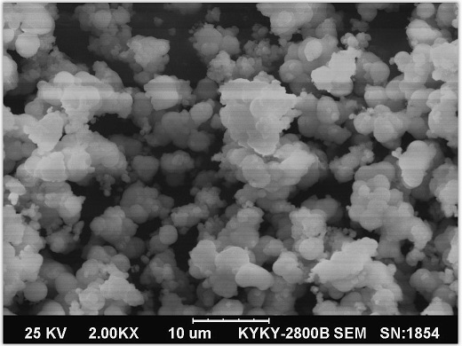
  • Preparation method of ferroboron alloy coated lithium iron phosphate
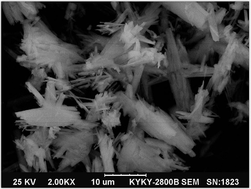
  • Preparation method of ferroboron alloy coated lithium iron phosphate
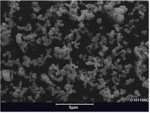
  • Preparation method of ferroboron alloy coated lithium iron phosphate

Examples


preparation example Construction

[0038] The properties of the finally obtained lithium iron phosphate are shown in Table 3:

[0039] Example 3

[0040] The properties of the finally obtained lithium iron phosphate are shown in Table 4:

[0041] Example 4

[0042] The properties of the finally obtained lithium iron phosphate are shown in Table 5:

[0043] Example 5

[0044] The properties of the finally obtained lithium iron phosphate are shown in Table 6:

[0045] Example 6

[0046] Table 7 Example 6 lithium iron phosphate product performance

[0047] The properties of the finally obtained lithium iron phosphate are shown in Table 8:

[0048] It can be seen from the above examples that the present invention eliminates or weakens the space charge effect by introducing a stable conductive buffer layer (iron-boron alloy), suppresses the generation of the interface layer, and reduces the interface resistance, thereby being suitable for use in solid-state battery materials; and due to the use of different T...

Embodiment 1

Embodiment 2


PUM

PropertyMeasurementUnit
particle diameteraaaaaaaaaa

Abstract

The invention relates to a preparation method of ferroboron alloy coated lithium iron phosphate, which comprises the following steps: respectively preparing ferrous phosphate and lithium phosphate, mixing the prepared ferrous phosphate and lithium phosphate, adding a hydrazine hydrate solution, grinding, drying, calcining, adding pure water into the obtained calcined material, grinding, and drying to obtain the ferroboron alloy coated lithium iron phosphate. Adding PEG (Polyethylene Glycol), ferrous sulfate crystals and EDTA (Ethylene Diamine Tetraacetic Acid) disodium into the obtained slurry, stirring and dissolving, continuously adding a sodium borohydride solution and a sodium hydroxide solution in a stirring state, maintaining the pH value in the process to be 8.5-10.5, reacting for 15-30 minutes, filtering, washing and drying in vacuum to obtain ferroboron alloy coated lithium iron phosphate. According to the invention, the metal alloy with better conductivity is adopted to realize coating, the conductivity is better, the interface resistance is lower, the corrosion resistance and the oxidation resistance are also very high, and the compaction density of the final product is also very high, so that the method is suitable for being applied to a solid-state battery material.

Description

technical field [0001] The invention belongs to the technical field of solid-state batteries, and relates to a method for preparing iron-boron alloy-coated lithium iron phosphate. Background technique [0002] In recent years, with the rapid development of portable electronic devices, electric vehicles and hybrid vehicles, research on energy storage materials with abundant resources, high energy efficiency and environmental friendliness has become an international research hotspot. In order to meet the large-scale market demand, it is far from enough to rely solely on the electrical properties of batteries to measure battery materials. Battery safety, manufacturing costs, energy consumption, and whether they cause environmental pollution have also become important indicators for evaluating battery materials. [0003] Solid state batteries are a type of battery technology. Unlike lithium-ion batteries and lithium-ion polymer batteries that are commonly used today, a solid-st...

Claims


Application Information

Patent Timeline
Patent Type & Authority Applications(China)
IPC IPC(8): H01M4/36H01M4/58H01M4/62H01M10/052
CPCH01M4/366H01M4/5825H01M4/626H01M4/628H01M10/052H01M2004/028H01M2004/021Y02E60/10C01B25/45B22F1/17
Inventor 王勤
Owner HUBEI WANRUN NEW ENERGY TECH DEV
Learn More