
Grain-oriented electrical steel sheet

An electromagnetic steel plate and directional technology, applied in the direction of circuits, magnetic objects, magnetic materials, etc., can solve the problems of not being able to fully obtain the iron loss reduction effect, and achieve the effect of improving the magnetic domain refinement effect, iron loss improvement, and improvement effect Effect

Active Publication Date: 2022-04-29
NIPPON STEEL CORP
View PDF13 Cites 0 Cited by
  • Summary
  • Abstract
  • Description
  • Claims
  • Application Information

AI Technical Summary

Problems solved by technology

Therefore, even if these technologies are adopted, the problem that the iron loss reduction effect cannot be sufficiently obtained cannot be sufficiently solved.

Method used


Image

  • Grain-oriented electrical steel sheet
  • Grain-oriented electrical steel sheet
  • Grain-oriented electrical steel sheet

Examples


Embodiment 1

[0170] In Example 1, the steel slab having the component composition shown in Table 1 was heated to 1150° C., and then subjected to hot rolling to obtain a hot-rolled sheet having a thickness of 2.6 mm. Next, about this hot-rolled sheet, the temperature of the first stage was set to 1100°C, and the temperature of the second stage was set to 900°C, and the hot-rolled sheet was annealed. Next, the hot-rolled sheet was subjected to primary cold rolling or multiple cold rolling including intermediate annealing to produce a cold-rolled sheet having a final thickness of 0.23 mm.

[0171] [Intention 1]

[0172]

[0173] Next, decarburization annealing and nitriding treatment (annealing to increase the nitrogen content of the steel sheet) were performed on the cold-rolled sheet having a final sheet thickness of 0.23 mm. The heating rate HR1 in the decarburization annealing was set to 100° C. / sec. The heating method was set to the radiant tube method. Here, t0 is 550°C, and t2 is...

Embodiment 2

[0183] In Example 2, the steel slab having the component composition shown in Table 1 was heated to 1150° C., and then subjected to hot rolling to prepare a hot-rolled steel sheet having a thickness of 2.6 mm. Next, about this hot-rolled sheet, the temperature of the first stage was set to 1100°C, and the temperature of the second stage was set to 900°C, and the hot-rolled sheet was annealed. Next, the hot-rolled sheet was subjected to primary cold rolling or multiple cold rolling including intermediate annealing to produce a cold-rolled sheet having a final thickness of 0.23 mm.

[0184] Next, decarburization annealing and nitriding treatment (annealing to increase the nitrogen content of the steel sheet) were performed on the cold-rolled steel sheet having a final sheet thickness of 0.23 mm. The heating rate HR in the decarburization annealing was set to 100° C. / sec. The heating method was set to the radiant tube method. Here, t0 is 580°C, and t2 is set to 860°C. In addit...


PUM

PropertyMeasurementUnit
Curie pointaaaaaaaaaa

Abstract

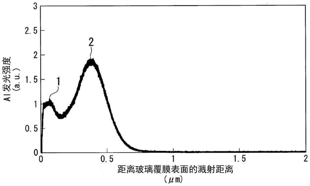
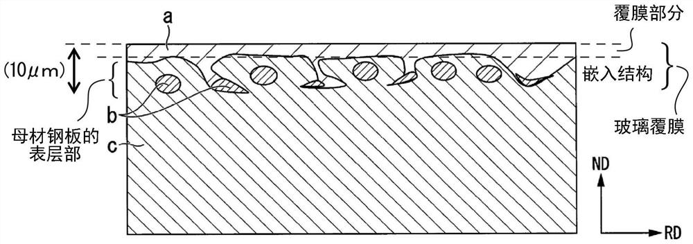
The purpose of the present invention is to provide a grain-oriented electrical steel sheet in which the iron loss before magnetic domain control is further improved, and in which the iron loss improvement effect can be sufficiently obtained even in heat-resistant magnetic domain control in which the iron loss improvement effect cannot be sufficiently obtained. According to one aspect of the present invention, provided is a grain-oriented electrical steel sheet characterized by comprising: a base steel sheet; and a glass coating film formed on the surface of the base steel sheet, the base steel sheet containing, in mass%, 0.010% or less of C, 2.00-4.00% of Si, 0.05-1.00% of Mn, 0.010-0.065% of Al, 0.004% or less of N, and 0.010% or less of S as chemical components, the remainder being Fe and impurities, the concentration of oxygen contained in the glass coating film and the base steel sheet being 2500ppm or less, the first peak intensity of Al in the concentration distribution of Al being IAl1, and the second peak intensity of Al in the concentration distribution of Al being IAl2. When the second peak intensity of Al is set as IAl2, the relationship of mathematical formula (1) is satisfied. Formula (1): IAl1 < IAl2.

Description

technical field [0001] The present invention relates to grain-oriented electrical steel sheets. Background technique [0002] Since the grain-oriented electrical steel sheet is mainly used as the iron core of a transformer, it is desired that the magnetization characteristics, especially the iron loss, be low. Therefore, it is important to align the crystal grains aggregated in the {110}<001> orientation to a high degree, to contain Si to increase the intrinsic resistance, and to reduce impurities. [0003] However, there is a limit to the reduction of iron loss due to the control of crystal orientation and the composition of the steel sheet, and a technique for reducing the iron loss by narrowing the width of the magnetic domain (hereinafter also referred to as "magnetic domain control technology") has been developed. ”). The magnetic domain control technology is roughly classified into a non-heat-resistant type and a heat-resistant type. [0004] As a non-heat-res...

Claims


Application Information

Patent Timeline
Patent Type & Authority Applications(China)
IPC IPC(8): C22C38/02C22C38/04C22C38/06C22C38/34C22C38/42C22C38/60C22C38/44C22C38/20C22C38/22C22C38/40C22C38/08C22C38/16C22C38/12C21D8/12C21D1/70H01F1/147
CPCC22C38/02C22C38/04C22C38/06C22C38/34C22C38/42C22C38/008C22C38/60C22C38/44C22C38/20C22C38/22C22C38/40C22C38/08C22C38/16C22C38/12C22C38/001C21D8/1222C21D8/1233C21D8/1244C21D8/1255C21D8/1277C21D8/1283C21D1/70H01F1/14766C21D2251/00C22C38/004C22C38/002H01F1/18H01F1/14783Y02P10/20C21D8/1216H01F1/147C21D6/002C21D6/005C21D6/008C21D8/005C21D9/46C22C2202/02
Inventor 安田雅人荒牧毅郎矢野慎也有田吉宏片冈隆史村上健一
Owner NIPPON STEEL CORP
Learn More