
Matrix type high-temperature gas cooler

A high-temperature gas and cooler technology, applied to indirect heat exchangers, heat exchanger types, heat exchanger shells, etc., can solve the problems of inconsistent length of heat exchange tubes, difficult coiling of finned tubes, and reduced service life of equipment, etc. problems, to achieve a high degree of uniform temperature distribution, reduce the difficulty of thermal design, and reduce the length of the process

Pending Publication Date: 2022-04-29
HEFEI GENERAL MACHINERY RES INST
View PDF1 Cites 0 Cited by
  • Summary
  • Abstract
  • Description
  • Claims
  • Application Information

AI Technical Summary

Problems solved by technology

[0003] The Chinese Patent Publication No. CN101943529.A discloses a high-temperature gas dry cooling device and method. The central heat exchange section of the patent adopts a cylindrical shell, and the heat exchange tubes are wound into coils. The lengths of the heat exchange tubes are inconsistent. The length of the external heat exchange tube is long, and the internal heat exchange tube is short. If the flow rate of the cooling medium is low, the cooling medium in the external heat exchange tube is easy to evaporate, resulting in dry burning, which greatly reduces the service life of the equipment; at the same time, the temperature of the high-temperature gas in the same section The uniformity of the distribution is poor; and the finned tubes are difficult to roll and the manufacturing cost is high
[0004] Chinese Patent Publication No. CN111854498A discloses a high-temperature gas cooler. The patent adopts a cylindrical shell in the central heat exchange section. The heat exchange tubes are arranged in the same direction in the cylindrical shell. The length of each heat exchange tube in the same section is The inconsistency makes the temperature distribution of high-temperature gas in the same section poor, and the thermal design of the heat exchanger is difficult at the same time; The layout makes the central heat exchange area longer, the pressure drop of high-temperature gas passing through the cooler is larger, and the equipment occupies a large area

Method used


Image

  • Matrix type high-temperature gas cooler
  • Matrix type high-temperature gas cooler
  • Matrix type high-temperature gas cooler

Examples


Embodiment Construction

[0055] The following will clearly and completely describe the technical solutions in the embodiments of the present invention with reference to the accompanying drawings in the embodiments of the present invention. Obviously, the described embodiments are only some, not all, embodiments of the present invention. Based on the embodiments of the present invention, all other embodiments obtained by persons of ordinary skill in the art without making creative efforts belong to the protection scope of the present invention.

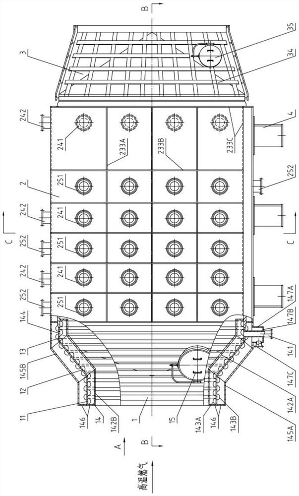
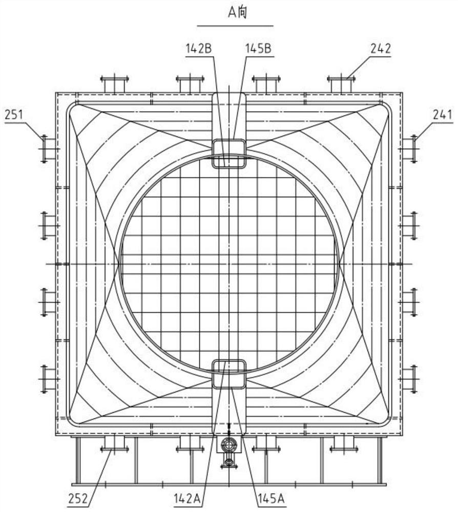
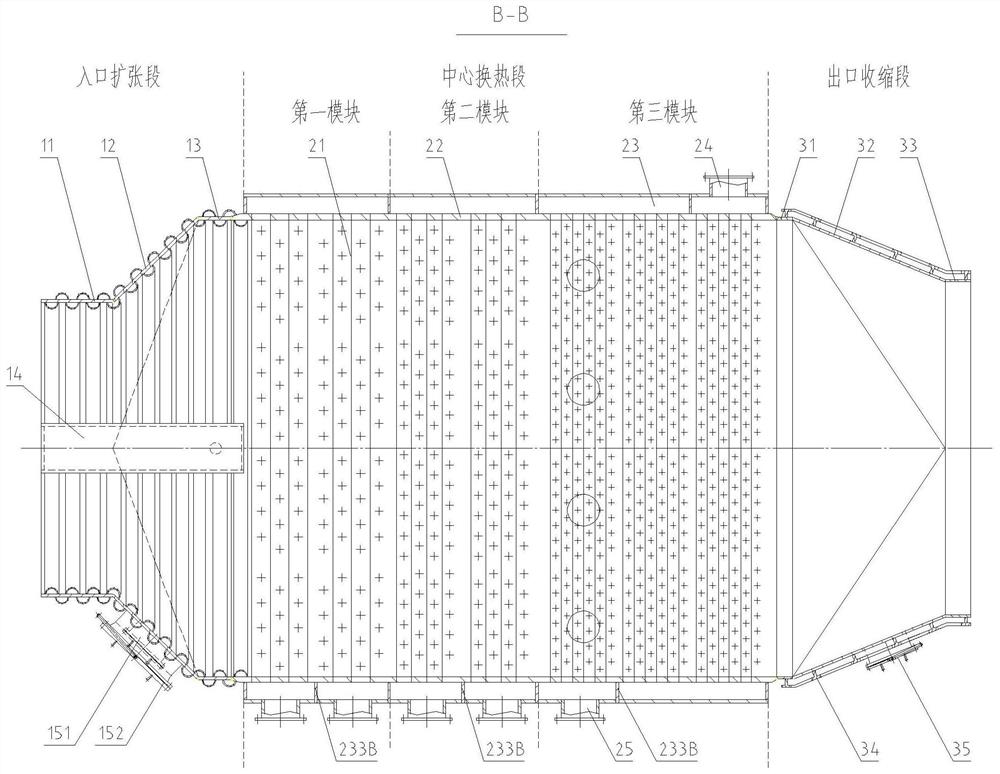
[0056] Depend on figure 1 As shown, in a matrix type high-temperature gas cooler of the present invention, the cold and hot medium exchange heat in reverse flow, the high-temperature gas flows in from the inlet expansion section 1 along the axis of the shell, and after heat exchange through the central heat exchange section 2, it shrinks from the outlet Section 3 flows out; the cooling medium flows into the heat exchange tube from the liquid inlet pipe of each...


PUM


Abstract

According to the matrix type high-temperature gas cooler, cold and hot media exchange heat in a staggered countercurrent manner, high-temperature gas flows outside heat exchange pipes in the axis direction of the cooler, and cooling media flow from the low-temperature ends of the high-temperature gas of all modules to the high-temperature ends of the high-temperature gas in the heat exchange pipes. The heat exchange tubes are light tubes, are arranged in a matrix mode and are arranged in the direction perpendicular to the flowing direction of high-temperature gas. According to the matrix type high-temperature gas cooler, the temperature distribution uniformity degree of high-temperature gas on the same section is high, the installation space can be reduced to the maximum extent, the thermotechnical design difficulty is reduced, no other structures are additionally arranged between the heat exchange pipes, the on-way length of the high-temperature gas is reduced to the maximum extent in the high-temperature gas flowing direction, and the heat exchange efficiency is improved. And the occupied area of the equipment is greatly reduced, unnecessary additional resistance is reduced, and the pressure drop of high-temperature gas in the equipment is reduced.

Description

technical field [0001] The invention relates to the technical field of high-temperature gas cooling, in particular to a matrix type high-temperature gas cooler. Background technique [0002] The high-altitude simulation test of the aero-engine is to use the method of simulating the total temperature and total pressure of the engine inlet and the ambient pressure of the engine outlet on the ground test equipment to simulate the air flight altitude and speed conditions of the engine. Many difficult problems encountered by engines used in modern high-performance aircraft in a wide range of flight work need to be solved through aero-engine simulated high-altitude flight tests. The high-temperature gas discharged from the engine in the test chamber is pressurized by the diffuser and then enters the cooler. After cooling, the high-temperature gas enters the exhaust system of the injection unit. The temperature of the gas discharged from the engine during the test in the test cham...

Claims


Application Information

Patent Timeline
IPC IPC(8): F28D7/16F28F9/04
CPCF28D7/1653F28F9/04
Inventor 邓靜陈永东王严冬吴晓红王林李超夏春杰
Owner HEFEI GENERAL MACHINERY RES INST
Learn More